Methods for forming a calibration standard and calibration standards for inspection systems

a technology of inspection system and calibration standard, which is applied in the direction of optical radiation measurement, instruments, photometry, etc., can solve the problems of large part of the yield loss of very large scale integrated circuit, large change in the size of the psl sphere, and large change in scattered light, so as to reduce the size accuracy of the deposition system used to deposit particles, eliminate uncertainty, and reduce the effect of the size accuracy

Inactive Publication Date: 2006-04-11
KLA TENCOR TECH CORP
View PDF7 Cites 39 Cited by
  • Summary
  • Abstract
  • Description
  • Claims
  • Application Information

AI Technical Summary

Benefits of technology

[0012]As described herein, the lateral dimension of the product standard particles is determined after the particles have been deposited on a specimen. Therefore, in an embodiment, an uncertainty of the lateral dimension of the product standard particles due to variations in a parameter of a system used to deposit the product standard particles may be approximately 0%, or may be substantially eliminated. The sizing accuracy of deposition systems used to deposit particles may be reduced by variations in particle charge uniformity. Therefore, in an additional embodiment, an uncertainty of the lateral dimension of the product standard particles due to variations in particle charge uniformity may be approximately 0%, or may be substantially eliminated.
[0013]Furthermore, an uncertainty of the lateral dimension of the product standard particles due to differences between the system used to deposit the product standard particles

Problems solved by technology

For example, defects caused by particles on a surface of a wafer are responsible for a substantial portion of the yield loss of very large scale integrated circuits.
There are several problems with PSL spheres as a calibration standard.
One problem is accurately determining the size of the spheres.
Changes in the size of the PSL spheres may produce a substantial change in scattered light.
Therefore, the accuracy of the PSL size will affect the accuracy of the defect sizes determined by the inspection system.
Variations in the refractive index of PSL spheres

Method used


Image

  • Methods for forming a calibration standard and calibration standards for inspection systems
  • Methods for forming a calibration standard and calibration standards for inspection systems
  • Methods for forming a calibration standard and calibration standards for inspection systems

Examples


example

Sizing Accuracy

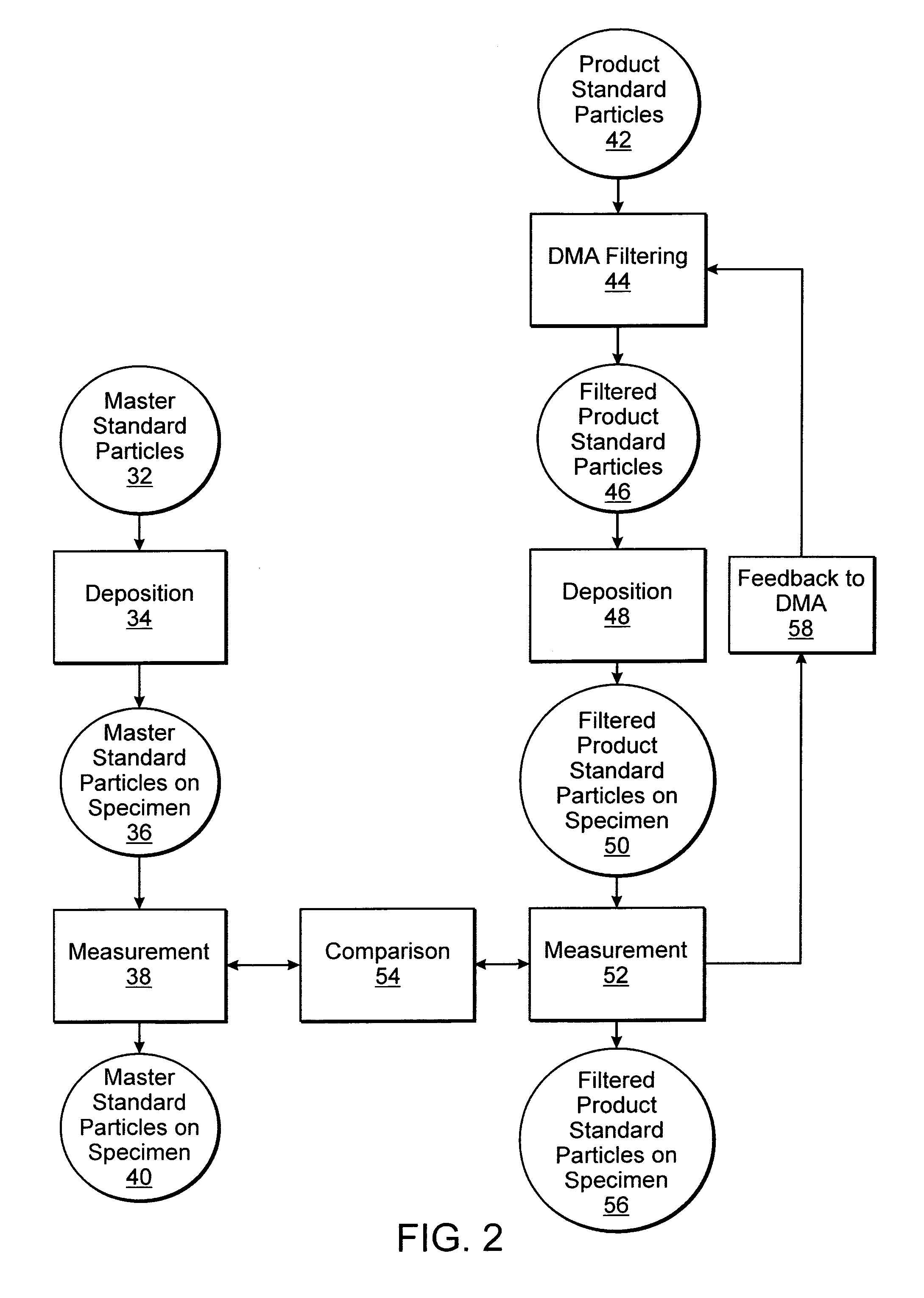
[0051]FIG. 4 is a plot of measured PSL sphere size versus wafer illustrating the sizing accuracy of an embodiment of a method for forming a calibration standard for an inspection system. The method that was used to generate the data in FIG. 4 is included here for example purposes only. The method illustrated in FIG. 2 may or may not include the following steps. A SurfScan SP1 DLS was selected to be calibrated and used for the entire process of forming the calibration standards (i.e., pre-scans, mid-scans, and post-scans). If the process is interrupted by other work or by an interval of time of more than one day, the calibration may or may not be repeated. To calibrate the SurfScan SP1 DLS, calibration wafers made with full wafer, direct (without DMA filtering) depositions of 60 nm and 83 nm PSL spheres were placed in a cassette. The two calibration wafers were scanned with oblique illumination, and scattered light was collected with a dark field, wide scatter angle ch...


PUM


Abstract

Methods for forming calibration standards for an inspection system and calibration standards are provided. One method includes scanning a first and a second specimen with an optical system. Master standard particles having a lateral dimension traceable to a national or international authority or first principles measurements are deposited on the first specimen. Product standard particles are deposited on the second specimen. In addition, the method includes determining a lateral dimension of the product standard particles by comparing data generated by scanning the two specimens. One calibration standard includes particles having a lateral dimension of less than about 100 nm deposited on a specimen. A distribution of the lateral dimension has a full width at half maximum of less than about 3%. The uncertainty of the lateral dimension is less than about 2%. Therefore, the standard meets the requirements for the 130 nm technology generation of semiconductor devices.

Description

BACKGROUND OF THE INVENTION[0001]1. Field of the Invention[0002]This invention generally relates to methods for forming a calibration standard and calibration standards for inspection systems. Certain embodiments relate to calibration standards that include particles having a lateral dimension that is certified after deposition of the particles on a specimen.[0003]2. Description of the Related Art[0004]Monitoring and controlling semiconductor fabrication processes by inspection and metrology have become increasingly important in the successful fabrication of advanced semiconductor devices as the dimensions of semiconductor devices continue to shrink with advances in semiconductor materials and fabrication processes. For example, defects caused by particles on a surface of a wafer are responsible for a substantial portion of the yield loss of very large scale integrated circuits. Currently available systems that may be used for inspection include systems configured to detect particle...

Claims


Application Information

Patent Timeline
IPC IPC(8): G01N21/88
CPCG01N21/93G01N21/4785G01N21/9501G01N21/94
Inventor SMITH, IANWOLTERS, CHRISTIANGUAN, YUBRAYTON, DON
Owner KLA TENCOR TECH CORP
Why Eureka
Try Eureka