
Storage capacitor with high memory capacity and low surface area

Inactive Publication Date: 2006-04-11
INFINEON TECH AG
View PDF11 Cites 17 Cited by
  • Summary
  • Abstract
  • Description
  • Claims
  • Application Information

AI Technical Summary

Benefits of technology

[0006]Within the context of the present invention, the storage capacitor comprises coupling capacitances of metals. Here, according to the invention, an inner electrode and an outer electrode of the storage capacitor are constructed from stacks enclosing metal pieces and the contact

Problems solved by technology

Because of the leakage currents, a storage capacitor slowly loses its charge which can lead to the loss of the information stored on the capacitor.

Method used


Image

  • Storage capacitor with high memory capacity and low surface area
  • Storage capacitor with high memory capacity and low surface area
  • Storage capacitor with high memory capacity and low surface area

Examples


Embodiment Construction

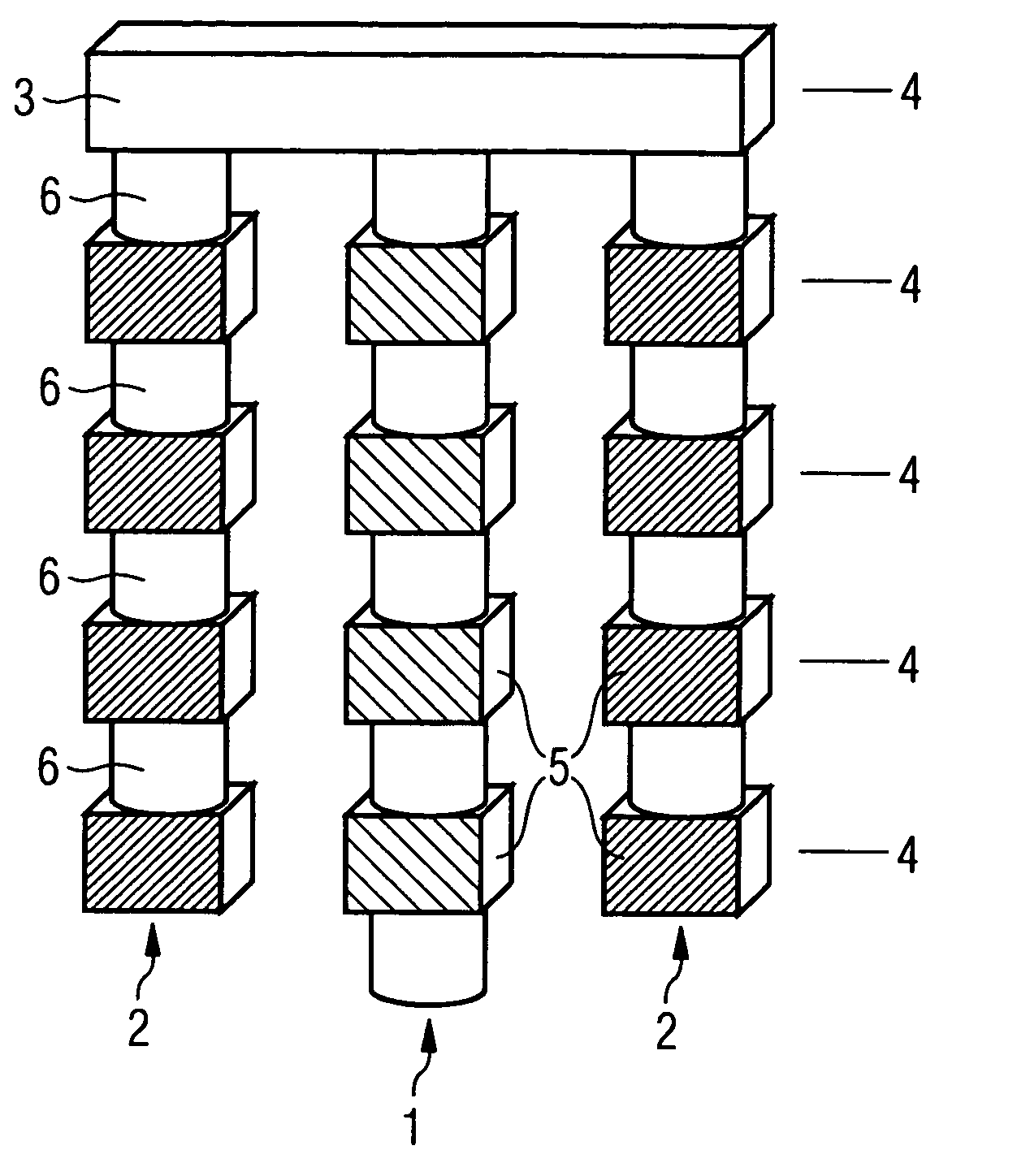
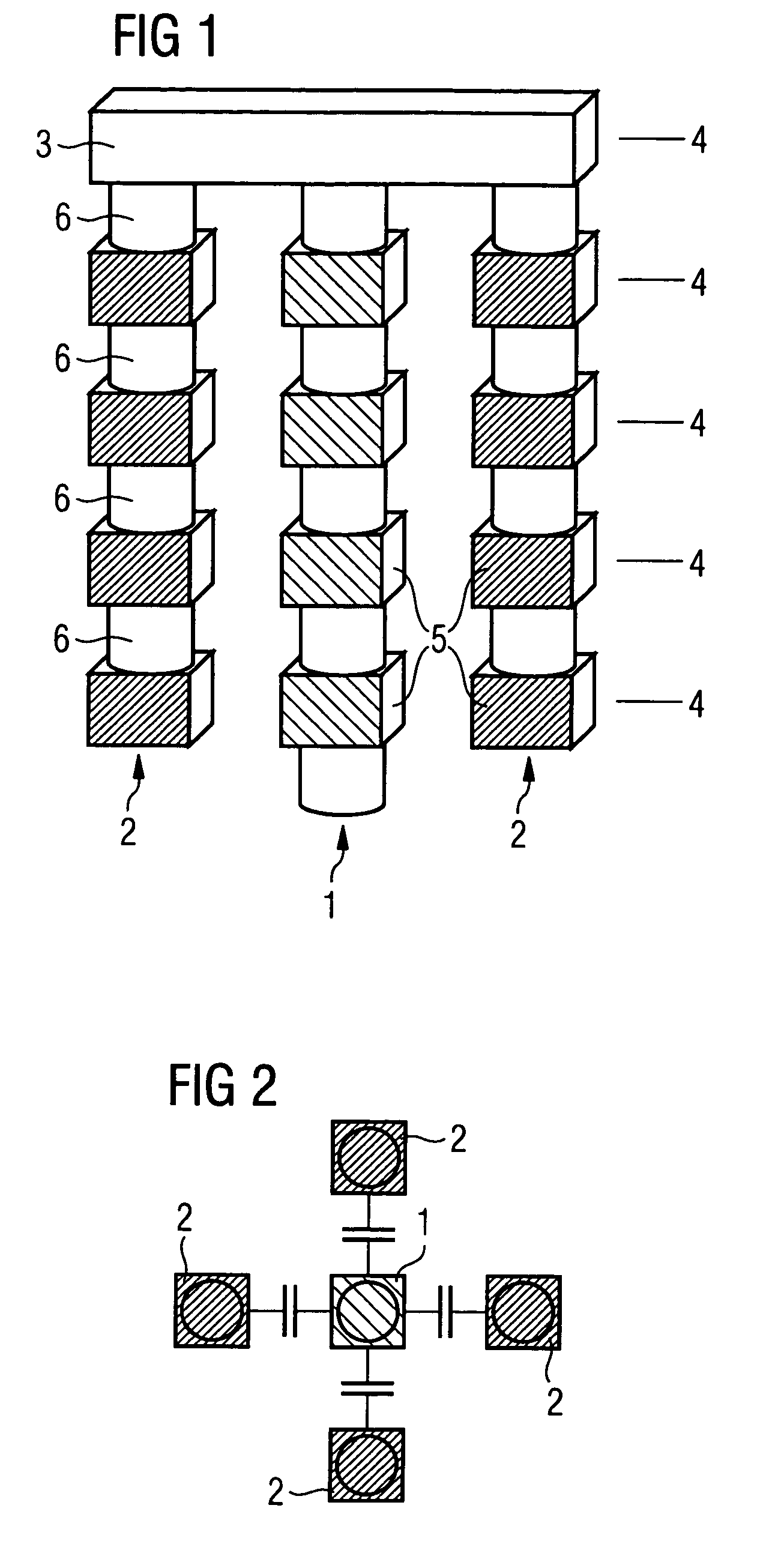
[0015]FIG. 1 shows a side view of a storage capacitor with an inner (first) electrode 1 in the centre, two adjacent outer (second) electrodes 2 and a metal part 3 connecting the outer electrodes.

[0016]In a manner according to the invention, lateral capacities between adjacent conductors are used to construct the storage capacitor. For this purpose, in each case a stack of metal parts 5 and contact elements 6 connecting these metal parts 5 is constructed, in order to form the corresponding electrode 1 or 2 of the storage capacitor, as shown in FIG. 1. Between a stack and an adjacent stack the desired memory capacity is then created, with the two stacks in particular being arranged in parallel.

[0017]When used in microelectronic circuits the metal parts 5 are so-called landing-pads and are each positioned in a metal layer 4. The contact elements 6 connecting the metal parts 5 are so-called vias and are positioned between the metal layers 4.

[0018]Advantages of this solution compared wit...


PUM


Abstract

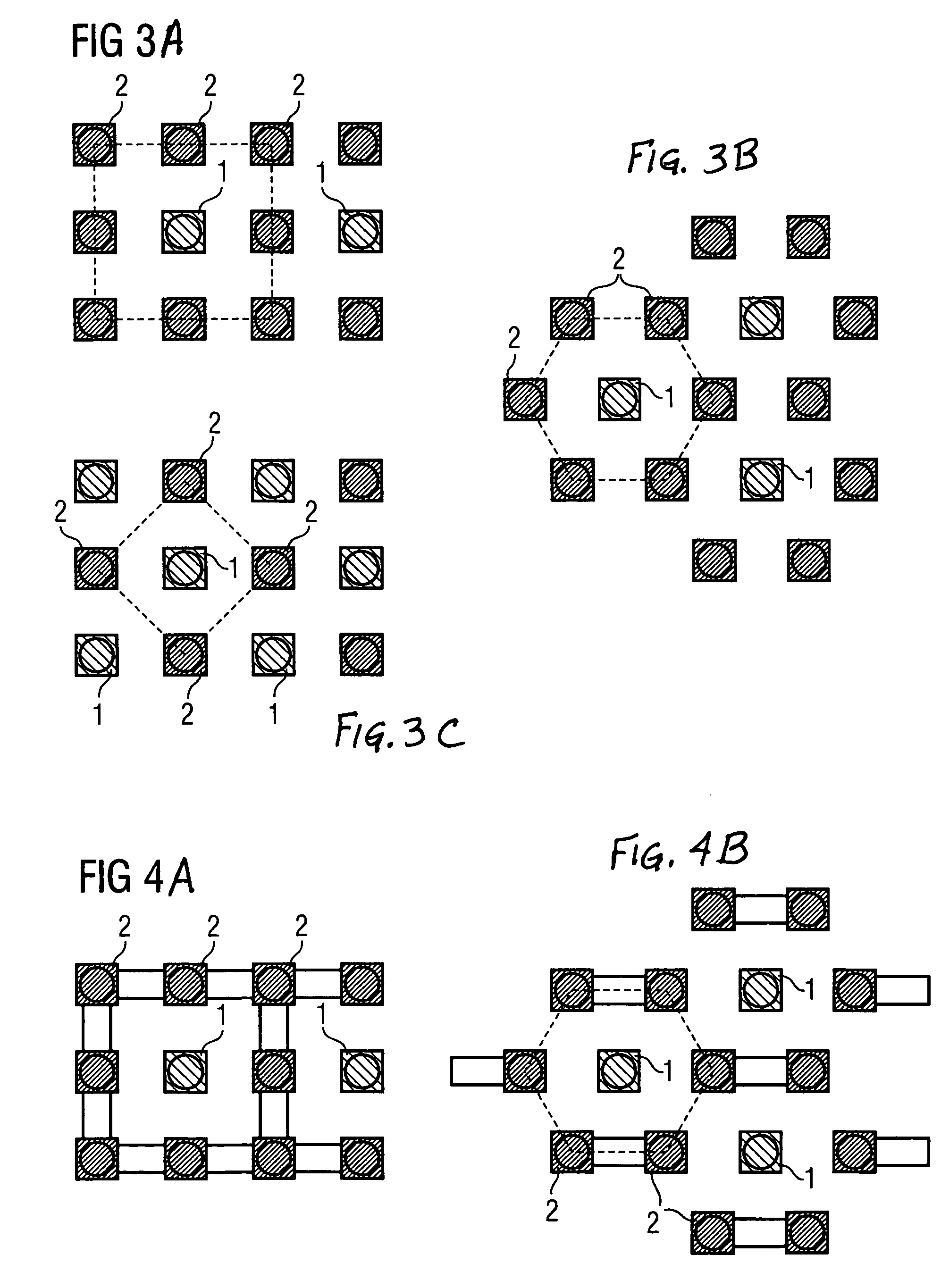
A storage capacitor includes at least one first electrode adjacent to at least one second electrode, whereby a lateral capacity is formed between these electrodes. The electrodes include stacks of metal parts and connecting contact elements. The second electrodes can be arranged around the first electrodes, and at least some of the second electrodes can be used jointly with adjacent ones of the first electrodes to form adjacent storage capacitors.

Description

FIELD OF THE INVENTION[0001]The present invention relates to a storage capacitor, in particular one that can be used for 1T-, 2T- and 3T-memory cells in, for example, system-on-chip applications, which provides the highest possible capacity with low surface area usage.BACKGROUND OF THE INVENTION[0002]In dynamic RAM memories, the information to be stored by a memory cell is generally held on a capacitor known as a storage capacitor. In system-on-chip applications in a pure logic technology, storage capacitors are often created by means of the gate capacity of an MOS transistor (e.g. a MoSyS-1T-SRAM, a 1T-cell of a static random access memory from MoSys Inc.) or by means of connection in parallel of gate and diffusion capacity (e.g. IFX-2T concept, a 2T-cell concept from Infineon).[0003]Because of the leakage currents, a storage capacitor slowly loses its charge which can lead to the loss of the information stored on the capacitor. In order to counter this, in microelectronic circuits...

Claims


Application Information

Patent Timeline
IPC IPC(8): H01G4/005H01L21/02H01L21/8242H01L21/8244H01L27/108H01L27/11
CPCH01L27/108H01L27/10805H01L28/90H01L27/11H01L27/1085H10B12/00H10B12/03H10B12/30H10B10/00
Inventor GEORGAKOS, GEORG
Owner INFINEON TECH AG
Learn More