
Data storage system with improved network interface

a data storage system and network interface technology, applied in the field of data storage systems with improved network interfaces, can solve the problems of high cost of multiple servers, uncoordinated operation of multiple servers, and inability to meet the needs of data storage, etc., to achieve faster and better-organized throughput

Active Publication Date: 2006-04-11
EMC IP HLDG CO LLC
View PDF8 Cites 25 Cited by
  • Summary
  • Abstract
  • Description
  • Claims
  • Application Information

AI Technical Summary

Benefits of technology

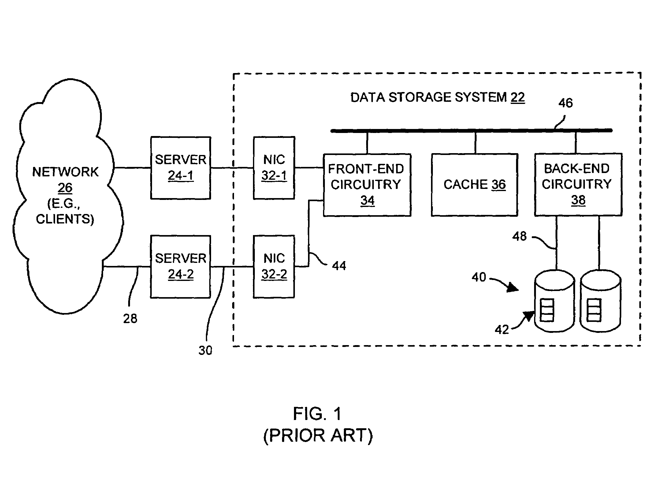
[0011]Additionally, the presence of the servers 24 provides another stage, or hop, for data to pass through (i.e., between the network 26 and the set of disk drives 40) thus adding some latency in moving data between the network 26 and the set of disk drives 40. Other stages include the NICs 32, the front-end circuitry 34, the cache 36, and the back-end circuitry 38.
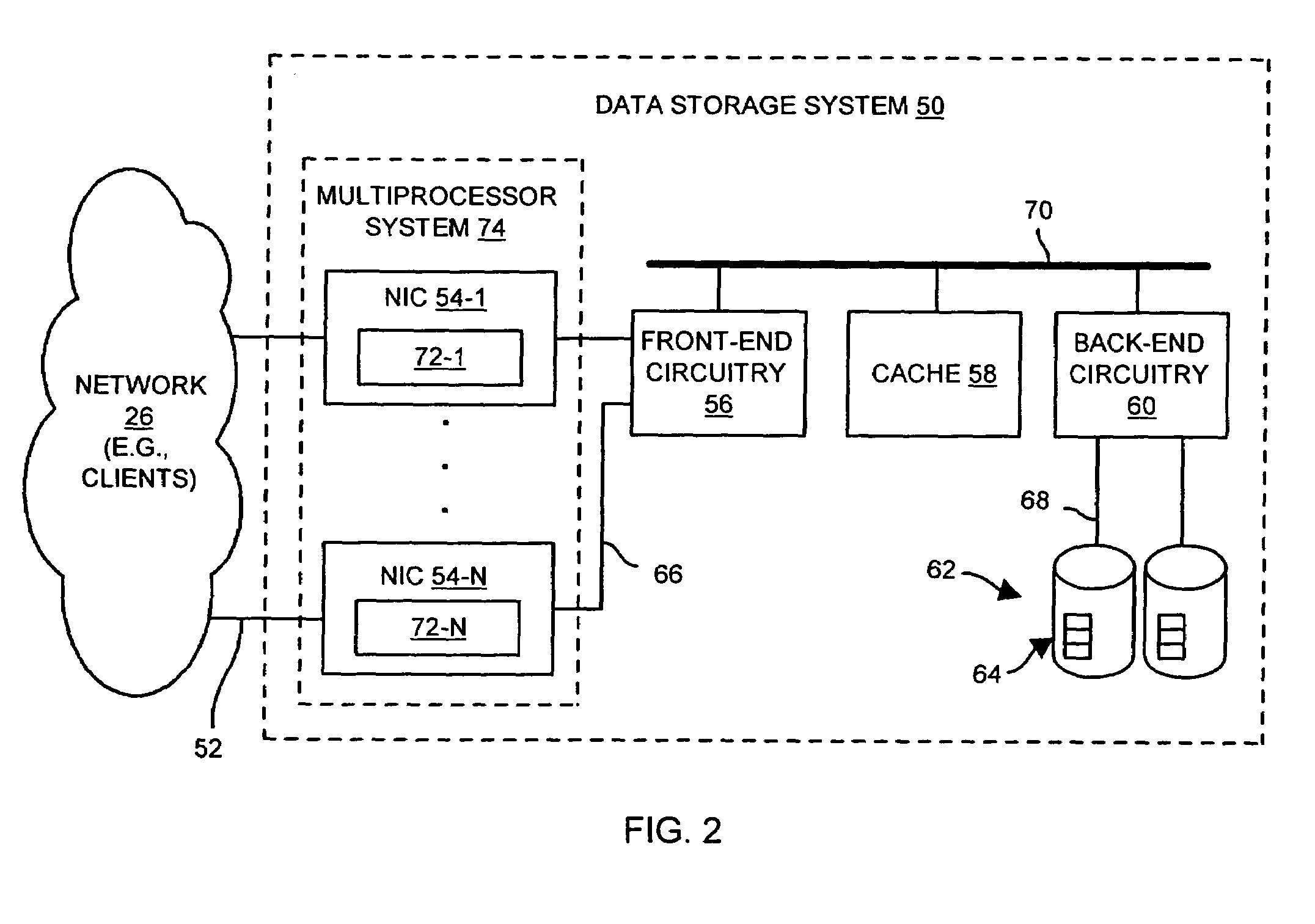
[0019]In one arrangement, the second port includes (i) a set of data pathway conductors that forms, between the control circuitry and the processing circuitry, a portion of a data pathway to carry data for storage within the data storage system, and (ii) a set of message pathway conductors that forms, between the control circuitry and the processing circuitry, a portion of a message pathway to carry messages for controlling storage of the data. In this arrangement, there are separate pathways for data and messages thus providing faster and better-organized throughput.

Problems solved by technology

Unfortunately, there are deficiencies to the above-described conventional configuration 20 of FIG. 1.
For example, the servers 24 of the configuration 20 can be expensive.
Furthermore, when there are multiple servers 24 operating as a front-end to the data storage system 22, the operation of the multiple servers 24 is typically not well-coordinated.

Method used


Image

  • Data storage system with improved network interface
  • Data storage system with improved network interface
  • Data storage system with improved network interface

Examples


Embodiment Construction

[0032]The invention is directed to data storage system techniques which utilize a network interface card (NIC) that is capable of operating as (i) an interface between file-based and block-based communications, and (ii) an application server that runs application-level programs. There is no need for an external server to translate file-based communications to block-based communications and vice versa since the NIC is capable of operating as an interface between file-based and block-based communications. Additionally, the data storage system can perform application-level operations (e.g., operate as a database engine that performs database queries) since the NIC is capable of operating as an application server that runs application-level programs. Accordingly, for a data storage system utilizing such a NIC, there is no need for one or more external servers to operate as a front-end to the data storage system (e.g., as required by the conventional data storage system configuration 20 ...


PUM


Abstract

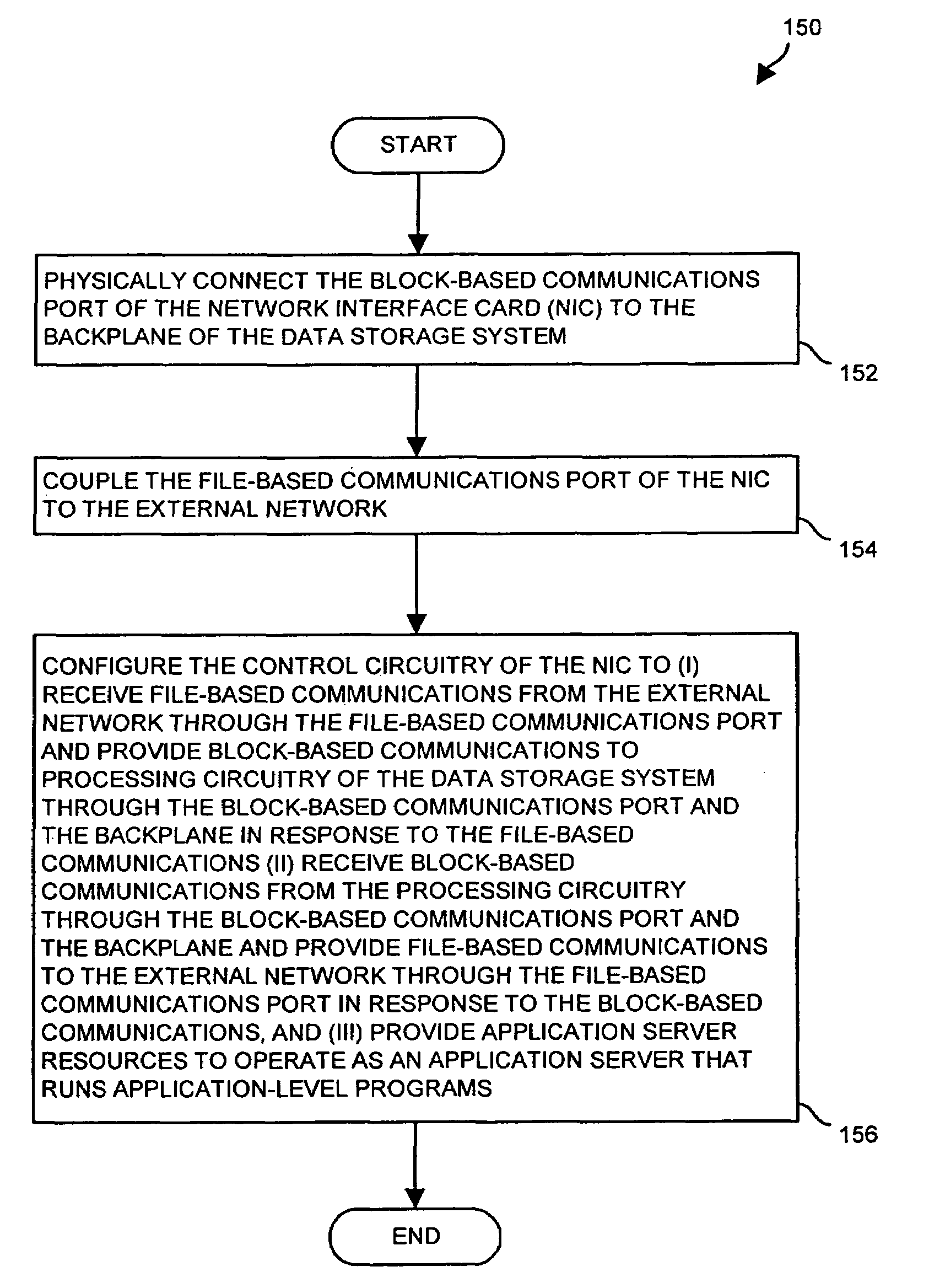
A data storage system has a backplane, processing circuitry and a NIC. The processing circuitry is physically connected to the backplane, and can perform block-based data access operations. The NIC has a first port that that couples to an external network, a second port that physically connects to the backplane, and control circuitry interconnected between the first port and the second port. The control circuitry can (i) receive file-based communications from the external network through the first port and provide block-based communications to the processing circuitry through the second port and the backplane in response to the file-based communications, (ii) receive block-based communications from the processing circuitry through the second port and the backplane and provide file-based communications to the external network through the first port in response to the block-based communications, and (iii) provide application server resources to operate as an application server that runs application-level programs.

Description

BACKGROUND OF THE INVENTION[0001]Typically, a data storage system operates as a large storage device for one or more external server computers (or simply servers) by responding to block-based input / output (I / O) requests that direct the data storage system to perform load and store operations. Examples of block-based communications include Block Mux Channel communications, Small Computer Systems Interface (SCSI) commands, Fibre Channel communications, Enterprise System Connection (ESCON) signals, Fibre Connectivity (FICON) Channel communications, and the like.[0002]A typical server provides services (e.g., client-oriented access to a data storage system) to one or more other computers called clients. In contrast to block-based communications which servers and data storage systems typically use to communicate with each other, clients and servers typically communicate with each other using client-oriented and server-oriented communications (hereinafter, generally referred to as client-...

Claims


Application Information

Patent Timeline
IPC IPC(8): H04L12/56H04L29/06
CPCH04L69/12
Inventor BARROW, JONATHAN J.CHILTON, KENDELL A.
Owner EMC IP HLDG CO LLC
Learn More