

Pump unit
a technology of pump unit and pump body, which is applied in the direction of fluid couplings, positive displacement liquid engines, couplings, etc., can solve the problems of troublesome assembly operation, unproposed effective proposals, and the temperature of the working hydraulic fluid between the hydraulic pump and the actuator, so as to shorten the length of the conduit and improve the efficiency. , the effect of lowering the manufacturing cos
- Summary
- Abstract
- Description
- Claims
- Application Information
AI Technical Summary
Benefits of technology
Problems solved by technology
Method used
Image

Examples
first embodiment
[0113]The first embodiment of the pump unit according to the first aspect of the present invention will be hereinafter described with reference to the accompanying drawings.
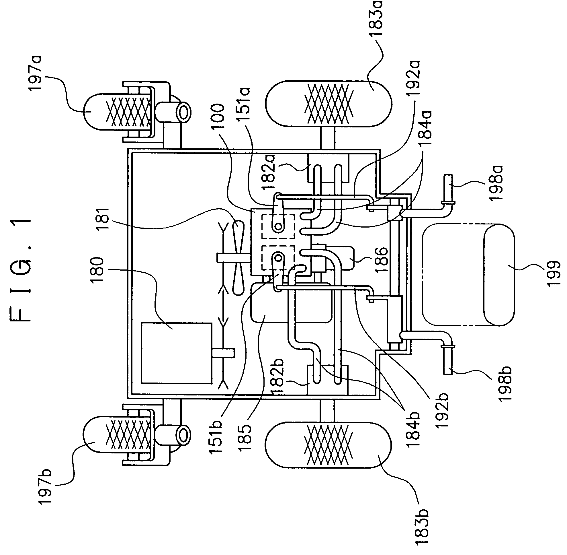
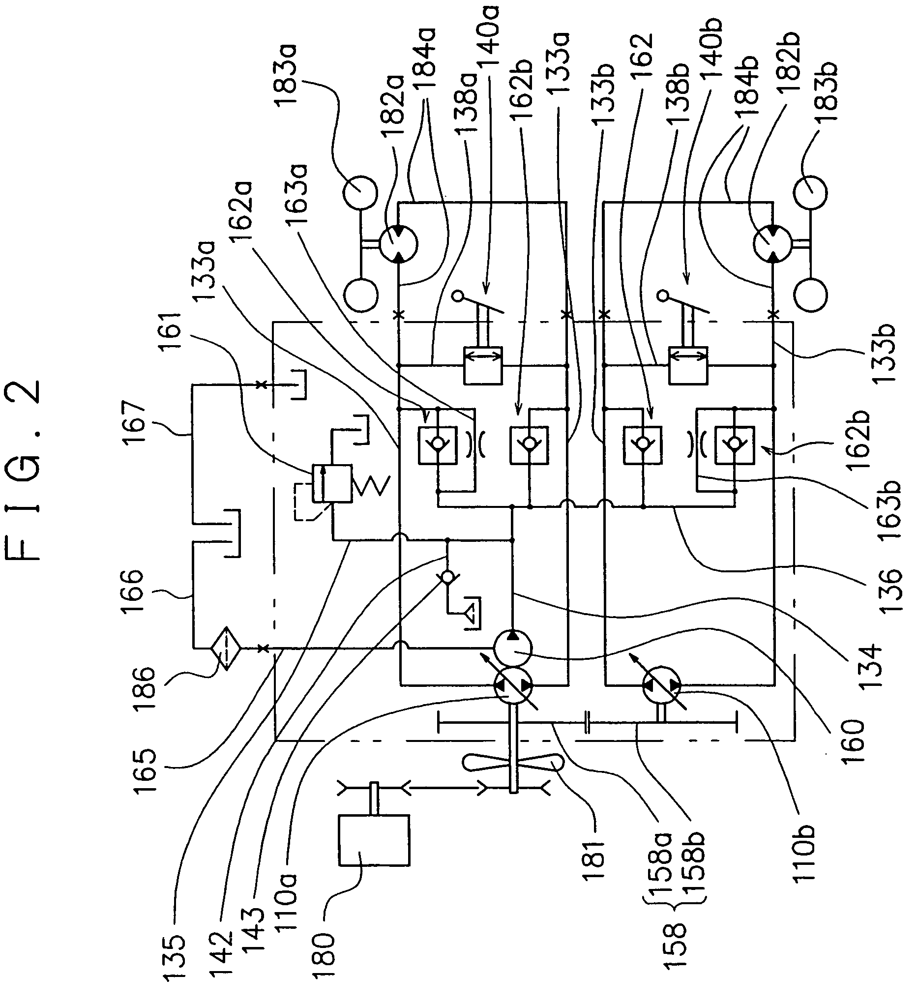
[0114]A pump unit 100 according to the first aspect of the present invention is designed to be operated in association with an actuator that is connected thereto via first and second pairs of hydraulic lines 184a and 184b and driven through an effect of pressurized hydraulic fluid in the pair of hydraulic lines. This embodiment will be described by taking for example the case that hydraulic motors 182a and 182b each are used as the actuator.
[0115]FIGS. 1 and 2 are respectively an expansion plan view of a vehicle to which the pump unit 100 of this embodiment is applied, and a hydraulic circuit of the vehicle. FIG. 3 is a cross sectional plan view of the pump unit and its periphery. FIG. 4 is a perspective view with a partially exploded portion of the pump unit. FIGS. 5 to 10 are respectively cross sections taken a...
second embodiment
[0181]The second embodiment of the first aspect of the present invention will be described with reference to FIG. 13. FIG. 13 is a longitudinal cross section of a first center section 131′ of a pump unit 100 according to this embodiment, which figure corresponding to FIG. 7 illustrating the aforementioned first embodiment.
[0182]In this embodiment, the first bypass line 138a and the second bypass line 138b are replaced by a single common line 138. In the following description, corresponding or identical parts to those of the first embodiment have been given the same reference characters or those with primes (′) to omit a detailed description thereof.
[0183]The common bypass line 138′ has a proximal end portion opening outwardly and a distal end portion communicating with all the first and second pairs of inlet / outlet passages 133a and 133b.
[0184]The common bypass line 138′ includes a single bypass valve 140′ to be operated from the outside of the first center section 131′ for the com...
third embodiment
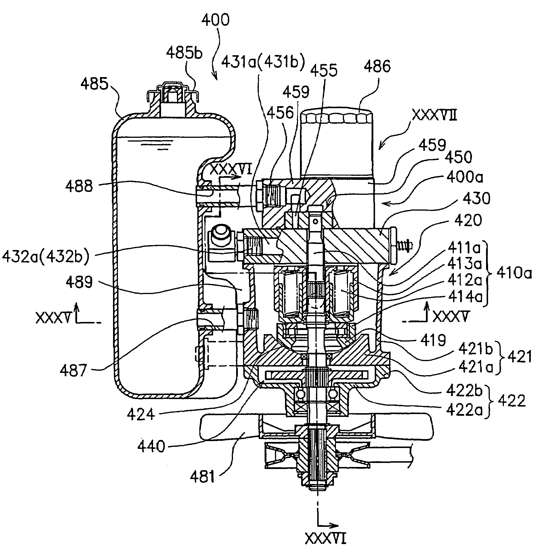
[0187]One embodiment of the pump unit according to the second aspect of the present invention will be hereinafter described with reference to FIGS. 15 to 19. FIG. 15 is a hydraulic circuit diagram of the vehicle to which a pump unit 200 of this embodiment is applied. FIG. 16 is a longitudinal cross-sectional front view of the pump unit and its periphery. FIGS. 17 to 19 are respectively cross sections taken along lines XVII—XVII, XVIII—XVIII, and XIX—XIX.
[0188]As illustrated in FIGS. 15 to 17, the pump unit 200 is adapted to be used in a vehicle having right and left drive wheels 283a and 283b to which first and second hydraulic motors 282a and 282b are respectively connected, and includes a first hydraulic pump 210a and a second hydraulic pump 210b respectively connected to the first and second hydraulic motors 282a and 282b via a first pair of hydraulic lines 284a and a second pair of hydraulic lines 284b, and a common housing 220 for accommodating these hydraulic pumps 210a and 21...
PUM
 Abstract
Description
Claims
Application Information