Electric heating type rolling device

a heating type and rolling device technology, applied in the field of rolling devices, can solve the problems of reducing productivity, difficult to carry out rolling, and prolonging the entire rolling process, so as to prevent overheating of metal strips and the resultant surface, the effect of improving the reduction ratio

Inactive Publication Date: 2006-04-18
KYONG IN SPECIAL METAL
View PDF9 Cites 12 Cited by
  • Summary
  • Abstract
  • Description
  • Claims
  • Application Information

AI Technical Summary

Benefits of technology

[0013]It is an object of the present invention to overcome the problems in the prior art and provide an electric heating type rolling device which improves reduction ratio and prevents overheating of a metal strip and resultant surface oxidization thereof by heating the same using a pulse current during a continuous rolling process.

Problems solved by technology

However, cold rolling necessarily requires an annealing process, so the entire rolling process time is lengthened and the productivity is lowered.
When the heating temperature is much lower than a specified one, many difficulties may occur such that it is hard to carry out rolling, excessive loads are imposed on the rolling device, and desirable properties cannot be obtained for the rolled strip.
However, if an excessively high temperature is set as the heating temperature, there is an increase in oxidization of the metal strip and an increase in energy costs is inevitable.
However, a high-frequency induction heating device is complicated, expensive and high power-consumptive.
However, the prior art electric heating type rolling device has a problem of consuming excessive power.
Further to such an excessive power-consumption, the steel strip is heated to a temperature ranging from 400° C. to 500° C., which causes oxidization and discoloration on the strip surface.
Also, because the work rolls are included in the electric circuit, the life of work rolls may be shortened due to electric corrosion, and a cooling device for preventing the work rolls from being damaged by heat transfer from the steel strip is additionally required.

Method used


Image

  • Electric heating type rolling device
  • Electric heating type rolling device
  • Electric heating type rolling device

Examples


first embodiment

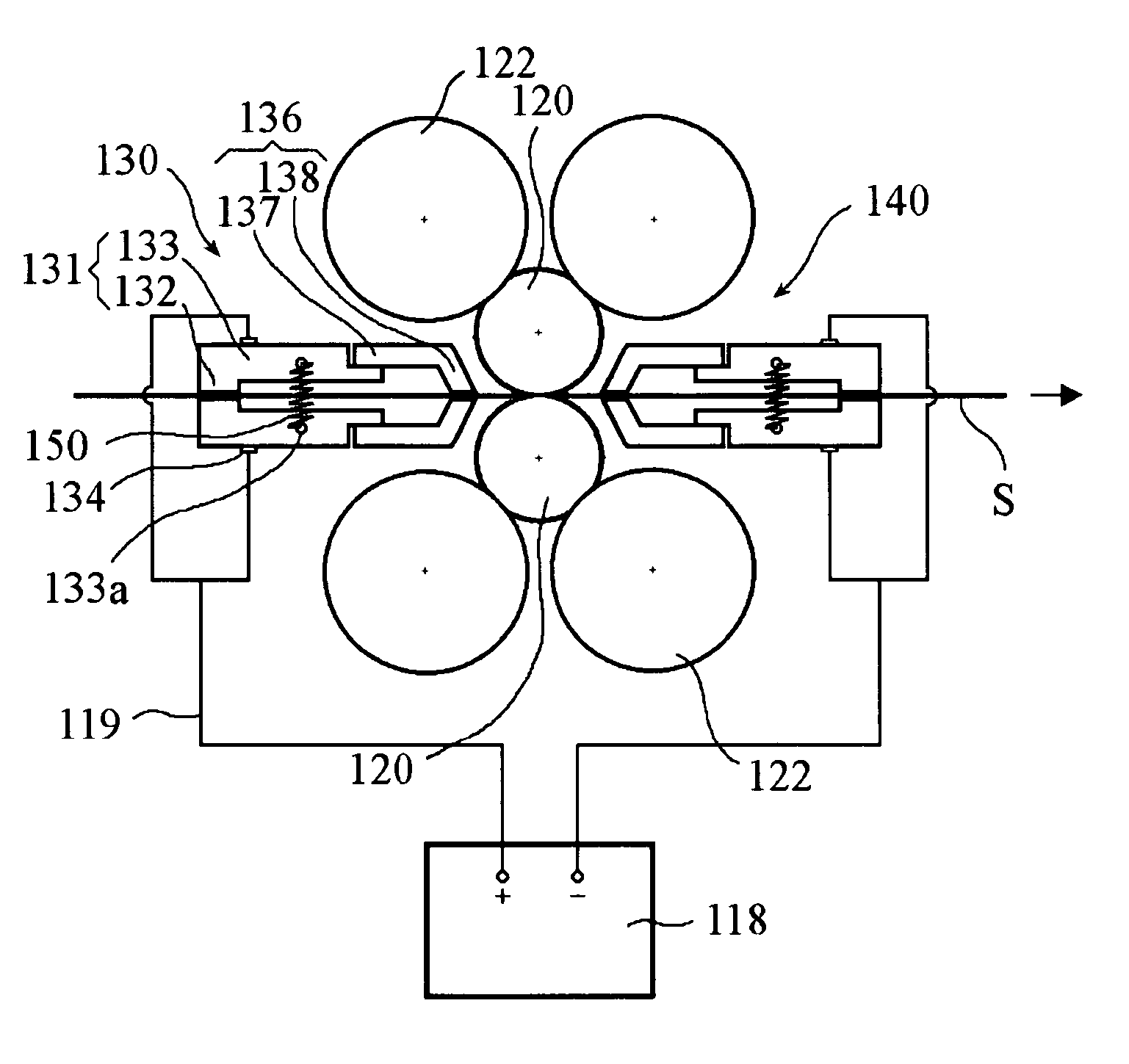
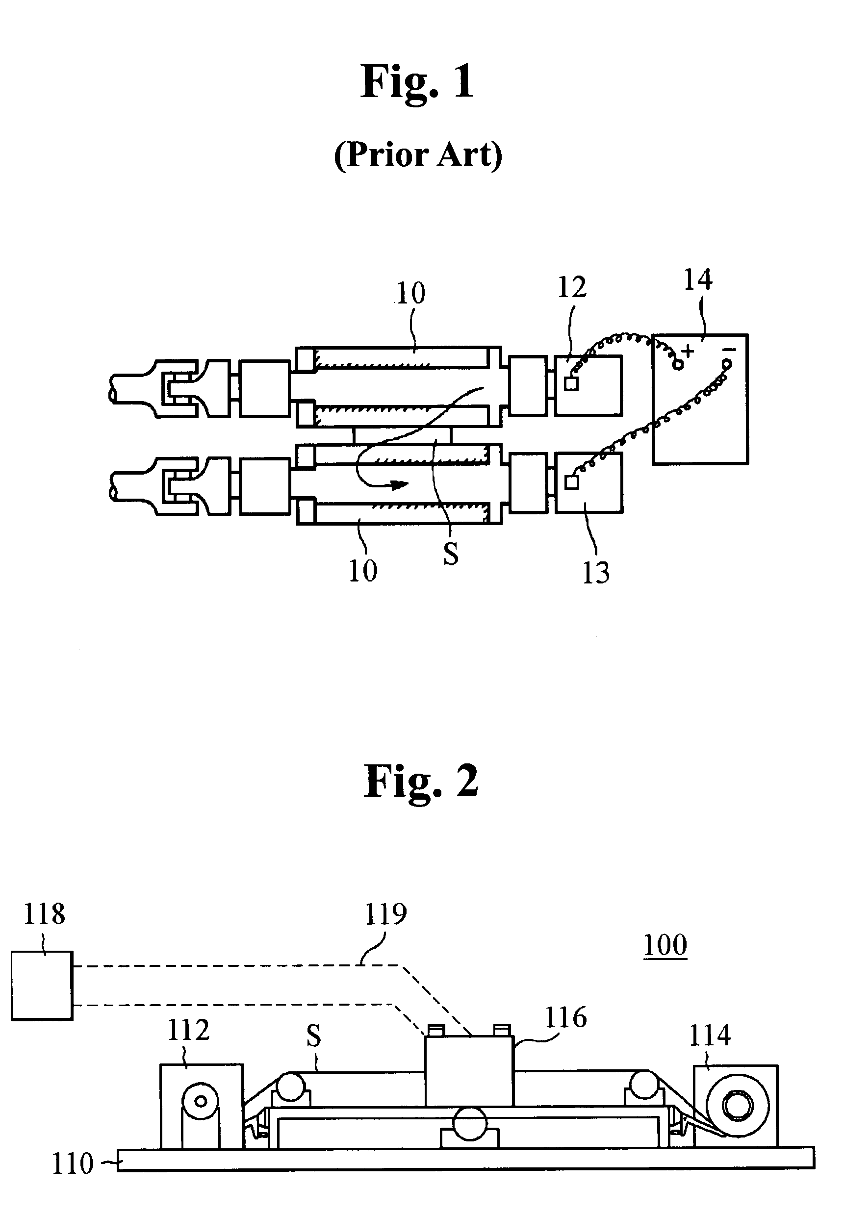
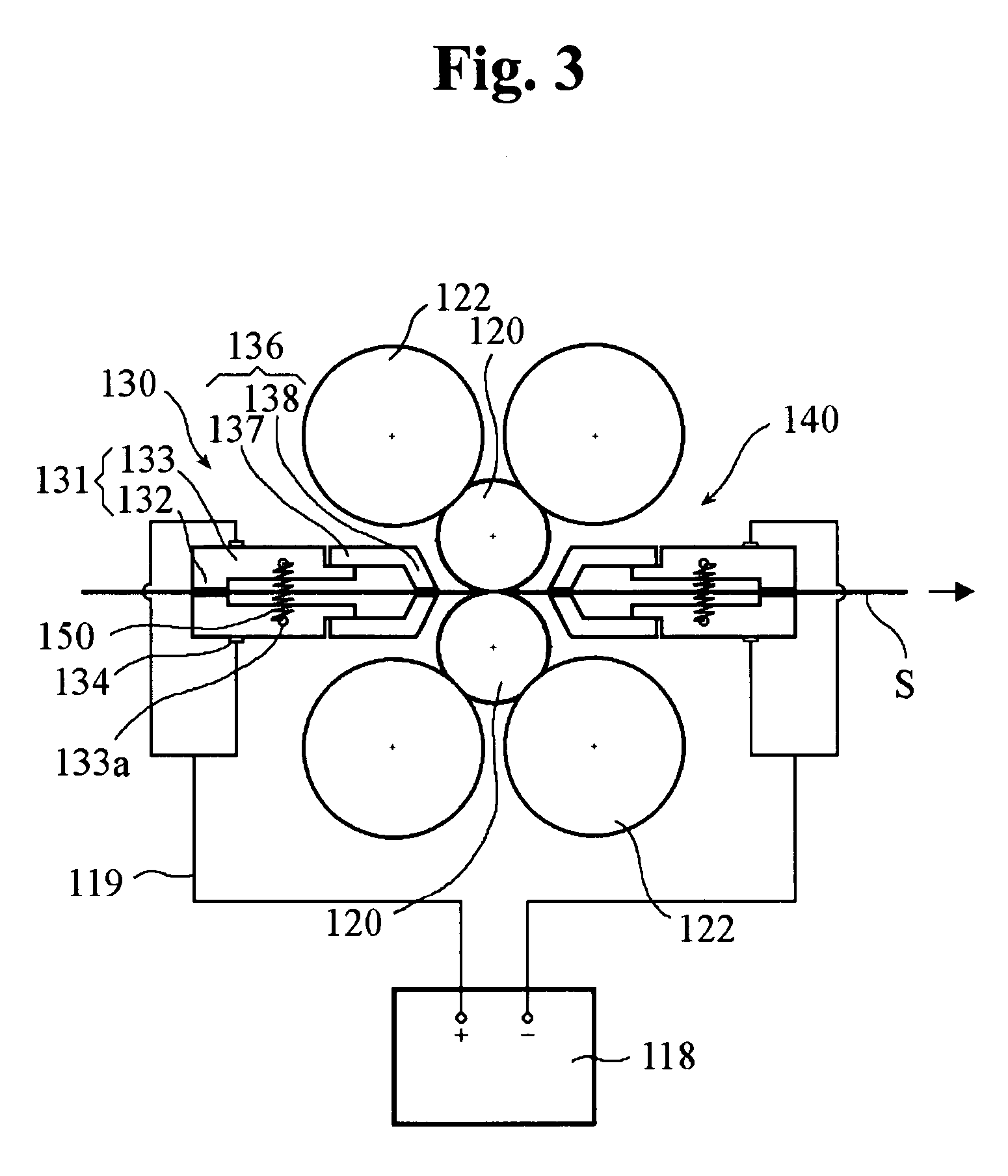
[0028]FIG. 2 is a front view showing an electric heating type rolling device in accordance with the present invention, and FIG. 3 shows schematically an inner structure of a roll stand of the electric heating type rolling device depicted in FIG. 2.

[0029]As shown in the drawings, an electric heating type rolling device 100 according to a first embodiment of the present invention comprises a base 110, front and rear strip reels 112 and 114 mounted on the base 110 for feeding a metal strip S, a roll stand 116 mounted between the strip reels 112 and 114, and a power supply 118 for generating a pulse current and supplying the same to the roll stand 116.

[0030]The roll stand 116 includes at least two pairs of support rolls 122 rotatably mounted, and at least one pair of work rolls 120 rotatably mounted for compressing and squeezing the metal strip S. One pair of support rolls 122 are disposed above the metal strip S, and the other pair of support rolls 122 are below the metal strip S. Each...

second embodiment

[0065]FIG. 6 shows a schematic for an inner structure of a roll stand of an electric heating type rolling device in accordance with the present invention.

[0066]As shown in the drawing, an electric heating type rolling device in accordance with the second embodiment of the present invention includes conductive electrode means which is implemented as a pair of “upstream” electrode rolls 160 connected electrically to the positive pole of the power supply 118 and a pair of “downstream” electrode rolls 170 connected to the negative pole of the power supply 118. Each pair of electrode rolls 160 and 170 contact the upper and lower surfaces of the metal strip S, and are disposed symmetrically to each other. The electrode rolls 160 and 170 are made from a material having a high heat-resisting property and conductivity. Diameters of the electrode rolls 160 and 170 are determined such that the rolls 160 and 170 are located as close as possible to the work rolls 120 with no interference therewi...

third embodiment

[0070]FIG. 7 shows schematically an inner structure of a roll stand of an electric heating type rolling device in accordance with the present invention.

[0071]As shown in the drawing, an electric heating type rolling device in accordance with a third embodiment includes conductive electrode means which is implemented as a pair of “upstream” contact members 130 connected electrically to the positive pole of the power supply 118. As another conductive electrode means, the upper and lower work rolls 120 are electrically connected to the negative pole of the power supply 118.

[0072]Accordingly, the power supply 118, the “upstream” contact members 130, the metal strip S and the work rolls 120 form a closed-circuit.


PUM

PropertyMeasurementUnit
widthaaaaaaaaaa
widthaaaaaaaaaa
temperatureaaaaaaaaaa

Abstract

An electric heating type rolling device comprises work rolls for rolling a metal strip, a power supply for generating a pulse current, a pair of upstream contact members which are disposed in a location before the metal strip passes through the work rolls, and a pair of downstream contact members which are disposed opposite to the upstream contact members in a location after the metal strip has been rolled by the work rolls and passed thereby. The contact members are electrically connected to the power supply. Each contact member includes a first contact portion contacting the metal strip, a flat portion which is extended from the first contact portion toward the work rolls while being spaced apart from the metal strip, and a second contact portion which is extended from the flat portion to contact the metal strip.

Description

FIELD OF THE INVENTION[0001]The present invention relates to a rolling device, and particularly to an electric heating type rolling device which improves reduction ratio and prevents overheating of a metal strip and resultant surface oxidization thereof by heating the same using a pulse current during a continuous rolling process.BACKGROUND OF THE INVENTION[0002]Generally, cold rolling refers to compressing and squeezing metal strips between work rolls at room temperature, and hot rolling refers to compressing and squeezing metal strips while applying heat.[0003]The advantages of cold rolling are good dimensional accuracy and surface finish. However, cold rolling necessarily requires an annealing process, so the entire rolling process time is lengthened and the productivity is lowered.[0004]In hot rolling, a metal strip is heated in a heating furnace, and is then fed to a rolling device. It is extremely important to heat the metal strip to a specified temperature before rolling. Whe...

Claims


Application Information

Patent Timeline
Patent Type & Authority Patents(United States)
IPC IPC(8): B21B27/06B21B9/00B21B13/14B21B27/08B21B45/00
CPCB21B45/004B21B13/147B21B27/08B21B9/00
Inventor KIM, STANISLAV KTROITSKY, OLEG AJEE, WON-GUK
Owner KYONG IN SPECIAL METAL
Why Eureka
Try Eureka