Transmission gear apparatus for motor vehicle

a transmission gear and motor vehicle technology, applied in the direction of electric generator control, electric propulsion mounting, gears, etc., can solve the problems of gear injury, adverse influence on etc., and achieve the effect of significantly prolonging the life of one-way clutches and reducing the impact torque applied to one-way clutches upon coupling

Inactive Publication Date: 2006-04-18
MITSUBISHI ELECTRIC CORP
View PDF18 Cites 65 Cited by
  • Summary
  • Abstract
  • Description
  • Claims
  • Application Information

AI Technical Summary

Benefits of technology

[0009]In the light of the state of the art described above, it is an object of the present invention to provide a transmission gear apparatus for a motor vehicle of a structure which can mitigate or reduce an impact torque taking place when the one-way clutch is closed or coupled after the start of engine operation while protecting the gears from injury by mitigating impact which may take place when an excessively large torque is applied to the internal gear at the time the internal gear is retained.
[0011]By virtue of the arrangement in which the one-way clutch is provided between the internal gear and the carrier, as described above, the impact torque applied to the one-way clutch upon coupling thereof can significantly be reduced when compared with the arrangement in which the one-way clutch is disposed between the carrier and the sun gear or between the internal gear and the sun gear, whereby the life of the one-way clutch can be significantly extended, to a great advantage.

Problems solved by technology

When the carrier and the sun gear are operatively coupled to each other through the one-way clutch, an impact torque of large magnitude occurs due to significant difference in the rotation speed between the carrier and the sun gear, which brings about remarkably adverse influence to the life of the one-way clutch, giving rise to a problem.
Furthermore, in the conventional transmission gear apparatus, neither measures nor means is provided for absorbing or mitigating the impact which takes place when an excessively large torque is applied to the internal gear for same reason upon retaining the internal gear by the ratchet mechanism, providing another problem that the gears are injured.

Method used


Image

  • Transmission gear apparatus for motor vehicle
  • Transmission gear apparatus for motor vehicle
  • Transmission gear apparatus for motor vehicle

Examples


embodiment 1

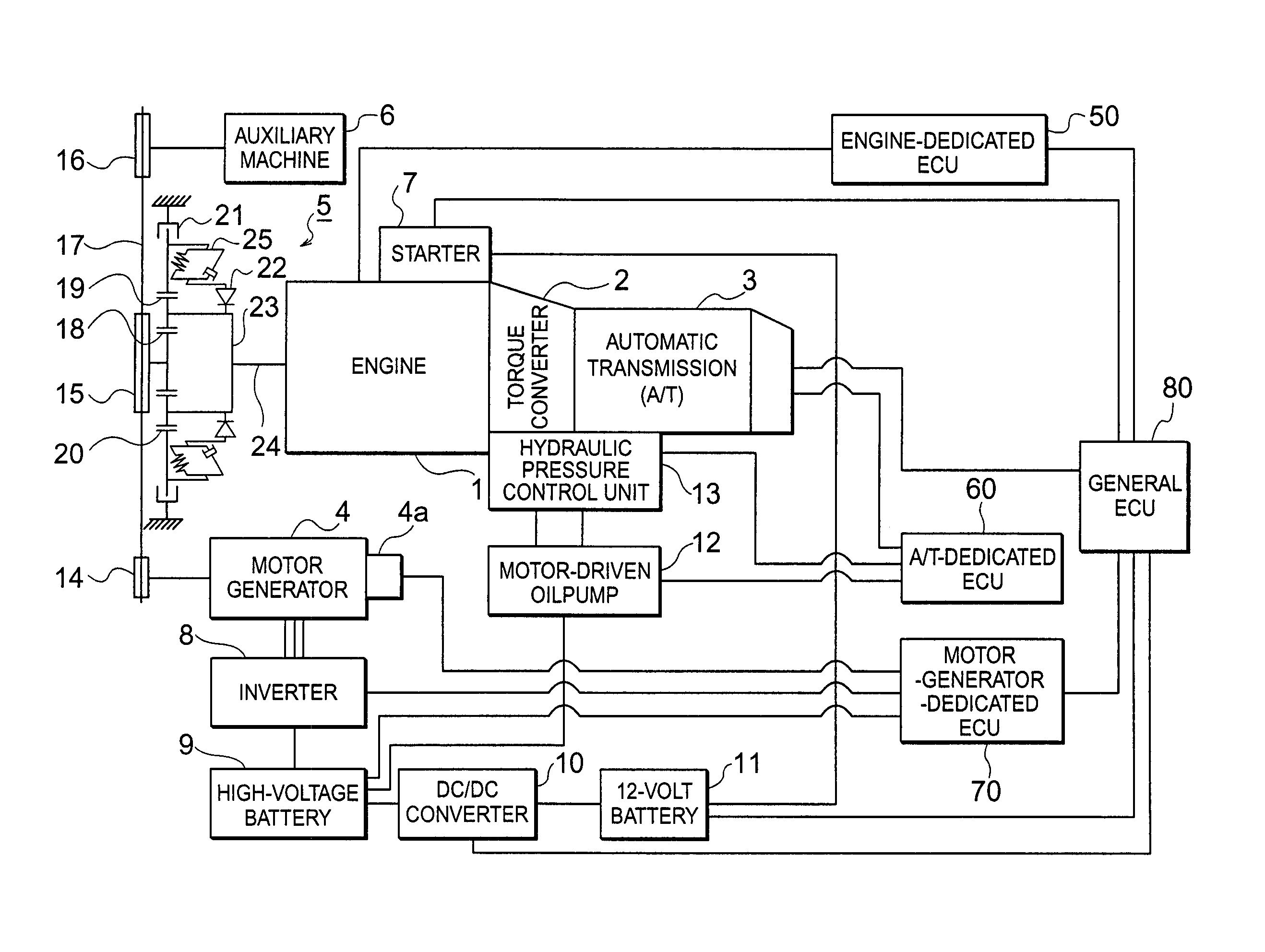
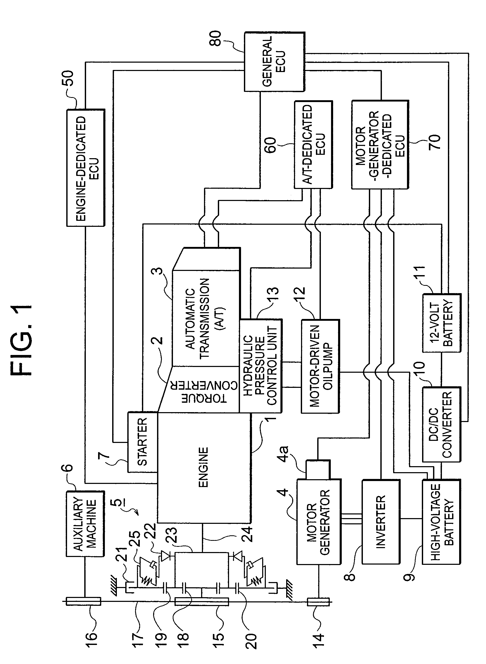
[0018]FIG. 1 is a block diagram showing a configuration of an internal combustion engine system for a motor vehicle inclusive of a transmission gear apparatus and peripheral devices. Referring to FIG. 1, the engine system includes an internal combustion engine (hereinafter also referred to simply as the engine) 1, a torque converter 2 equipped with a lock-up mechanism, an automatic transmission (hereinafter also referred to as A / T in abbreviation) 3 and a motor generator 4, i.e., a dynamo-electric machine designed to operate exhangeably as an electric motor and an electric generator. The motor generator 4 is equipped with a rotation sensor 4a.

[0019]Further referring to FIG. 1, a transmission gear apparatus generally denoted by reference numeral 5 is provided. In an engine starting operation mode, the transmission gear apparatus 5 receives a turning force or torque outputted from the motor generator 4 through a motor-generator pulley (dynamo-electric machine pulley) 14, a belt (powe...


PUM


Abstract

A transmission gear for an automobile includes a dynamo-electric machine operating as a motor and a generator, a dynamo-electric machine control device, a dynamo-electric machine pulley, an auxiliary machine pulley, a crank pulley rotatable relative to or integrally with the crank shaft, a sun gear coupled to the crank pulley, planetary gears each rotatable and revolvable along an outer periphery of the sun gear, a carrier for supporting the planetary gear rotatably and revolvably and connected to the crank shaft, an internal gear meshing with the planetary gear, an electromagnetic clutch for changing over the internal gear between restrained and unrestrained states, an electromagnetic clutch changeover control device, and a one-way clutch provided between the internal gear and the carrier.

Description

BACKGROUND OF THE INVENTION[0001]1. Field of the Invention[0002]The present invention generally relates to a transmission gear apparatus for an automobile or a motor vehicle. More particularly, the present invention is concerned with a transmission gear apparatus for the motor vehicle which can ensure proper transmission gear ratios (also referred to as change gear ratio) for an engine starting operation effected by means of a dynamo-electric machine and an auxiliary machine driving operation performed by an internal combustion engine.[0003]2. Description of Related Art[0004]In a hitherto known or conventional transmission gear apparatus for the motor vehicle disclosed, for example, in Japanese Patent Application Laid-Open Publication No. 264153 / 1990 (JP-A-2-264153), a pulley mounted on a rotatable shaft of the starter motor and a crank pulley connected to a crank shaft of an internal combustion engine (hereinafter also referred to simply as the engine) through the medium of a plane...

Claims


Application Information

Patent Timeline
Patent Type & Authority Patents(United States)
IPC IPC(8): B60K1/00B60W10/08B60W10/30B60W30/188F16H3/54H02P9/04
CPCB60K6/48B60W10/08B60W30/1888B60W10/30Y02T10/6221F16H3/54Y02T10/62
Inventor ODAHARA, KAZUHIROKITAMURA, YUTAKA
Owner MITSUBISHI ELECTRIC CORP
Why Eureka
Try Eureka