Wear bars for impellers

a technology of wear bars and impellers, applied in the field of wear bars for impellers, can solve the problems of delay in use of the apparatus, wear of components, and the need for repair and replacement of components, and achieve the effect of reducing the size and shap

Inactive Publication Date: 2006-04-18
KENNAMETAL INC
View PDF10 Cites 21 Cited by
  • Summary
  • Abstract
  • Description
  • Claims
  • Application Information

AI Technical Summary

Benefits of technology

[0014]An impeller assembly for crushing earth materials such as rock into desirable shapes and sizes. The impeller assembly assists in projecting and directing an aggregate flow against, over or around another embodiment of a body (e.g., anvil) designed for crushing, fracturing, breaking up and reducing in size and shape large aggregate into smaller sizes and shapes.

Problems solved by technology

Regardless of the precise nature or function of an apparatus in which components are subjected to wear by a material flow, wear causes need for repair and replacement of components and delays in use of the apparatus while one or more worn components are identified, inspected, removed, and replaced.
Wear of components adds to the expense of maintaining and operating the apparatus.
As a result of persistent wear caused by material flows, components on construction equipment exposed to material flow must be replaced.
Replacement of components causes “down time” to repair, refit, and replace components.
Additional expenses are associated with replacing the worn part or component, inventorying replacement components, and delivering a replacement component to what is often a remote site.
Both the central feed body and impeller shoes on the impact impellers are subjected to substantial wear caused by material flow.
The normal force against the surface of the shoe results in high friction and high wear rates of the shoe.
U.S. Pat. No. 5,954,282 and other impact crushers, are subject to abrasion, decomposition, fracture, friction, impact, pulsation, wave action, grinding, and other actions causing wear to components of an impact crusher this is due to the velocity, acceleration and composition of aggregate flows against, across, and around the components during operation of a crusher (collectively, “wear”).
As the body ferrous material recedes, the interference press fit between the ferrous body and rods shorten and weaken until eventually on account of the weakened joint the rods are then easily knocked out by aggregate.
In efforts to protect hard material rods from wash out, prior designs have attempted to position adjacent hard material rods closer together, but have been unsuccessful.
In these prior designs it was necessary that the spacing between the rods became so small that the strength and integrity of the ferrous body for receiving and holding (interference fit) the insert rods weakened and softened to the point that the interference fit was insufficiently strong to hold the rods in place.
The hard material rods cause damage to the components of the impeller that are often made of softer materials.
These compact rods that broke free of the impeller or shoes were hurled against the anvils and other components of the vertical shaft impeller (VSI) causing accelerated wear and greater damage to the VSI as the compact inserts bounce back and are constantly flung within the impeller against anvils and other components.
On occasion such compact inserts would knock loose other compact inserts resulting in more destruction and even greater acceleration of damage within the VSI.

Method used


Image

  • Wear bars for impellers
  • Wear bars for impellers
  • Wear bars for impellers

Examples


Embodiment Construction

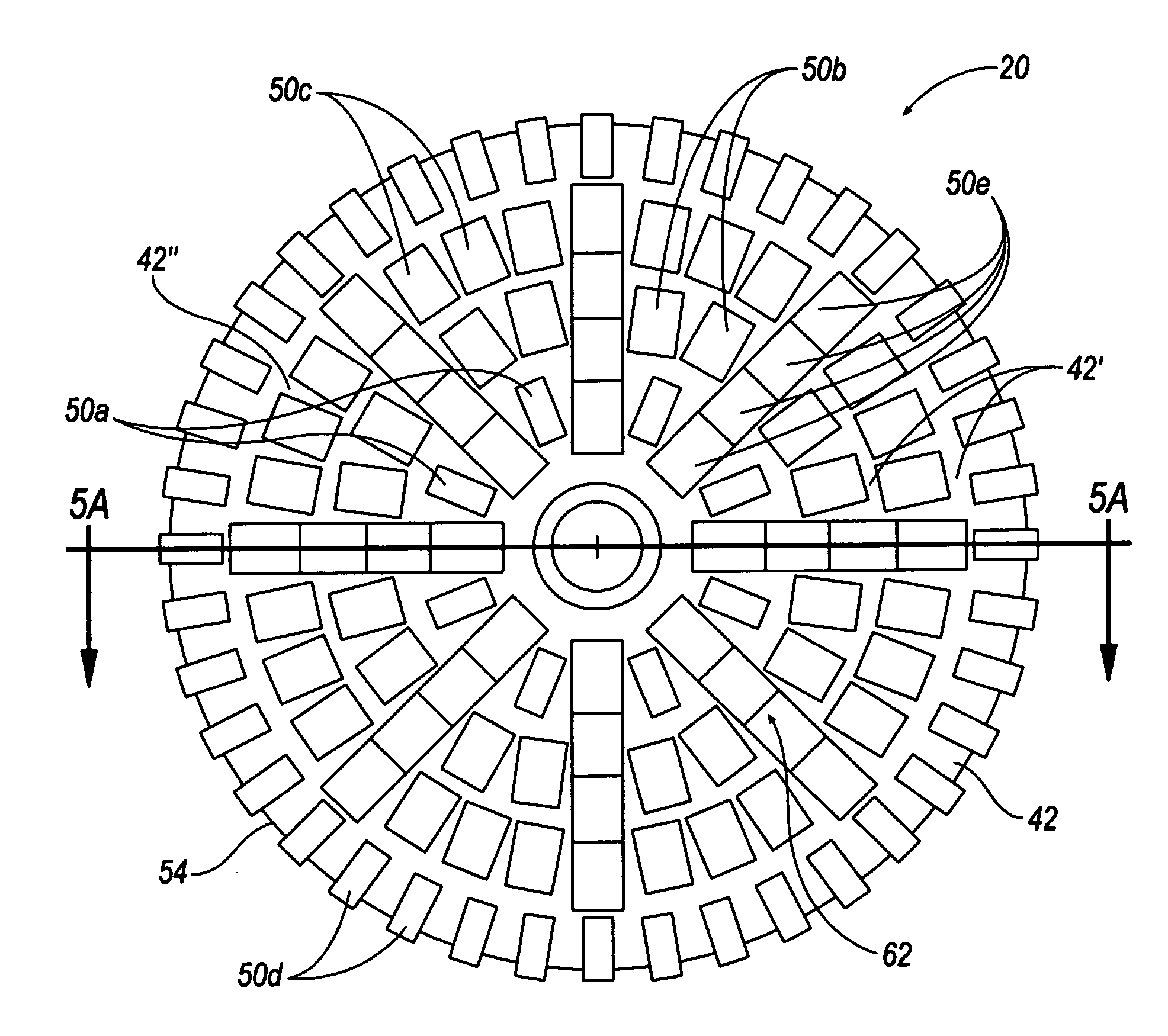
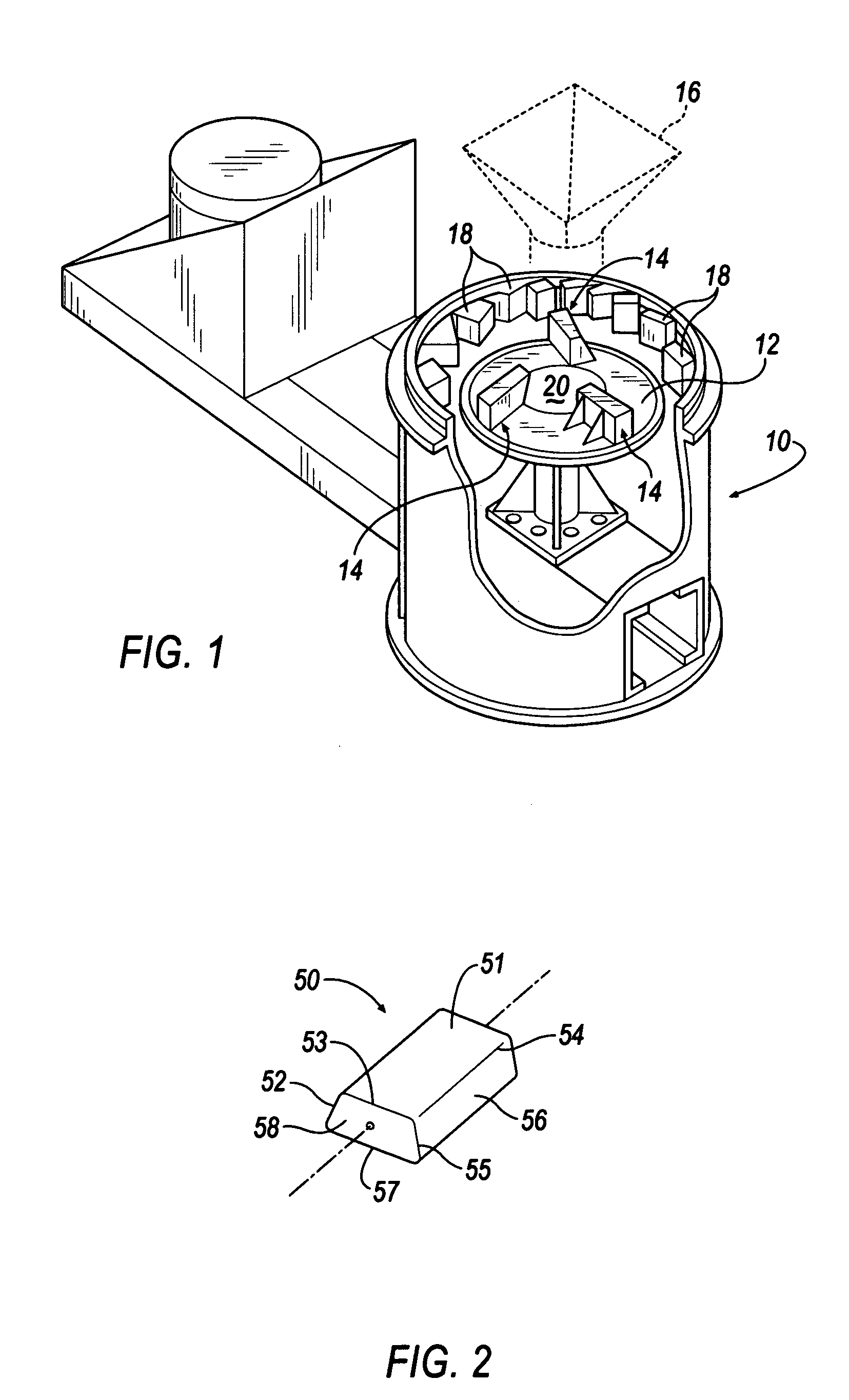
[0030]Referring now to FIG. 1, a vertical shaft impeller rock-crushing machine 10 includes an impeller turntable 12 which revolves at a high speed about a central shaft (not shown). Impeller blade shoes 14 are affixed to the turntable 12 at regular intervals along its surface. Rock or other aggregate (not shown) drops onto the turntable from a funnel 16 located above the turntable, and the centrifugal force caused by the rotating shoes 14 slings the rock outwards causing it to strike a series of anvils 18 and be crushed. Initially the rock or aggregate falls on a central feed body 20 of the turntable 12 but as the turntable is rotating, the rock spreads outward along the central feed body 20 forming streams of material, particulate in nature, which flow across the wear surfaces of each of the impeller blade shoes 14. The impeller shoes 14 and central feed body are mounted to the impeller table by methods well known in the industry.

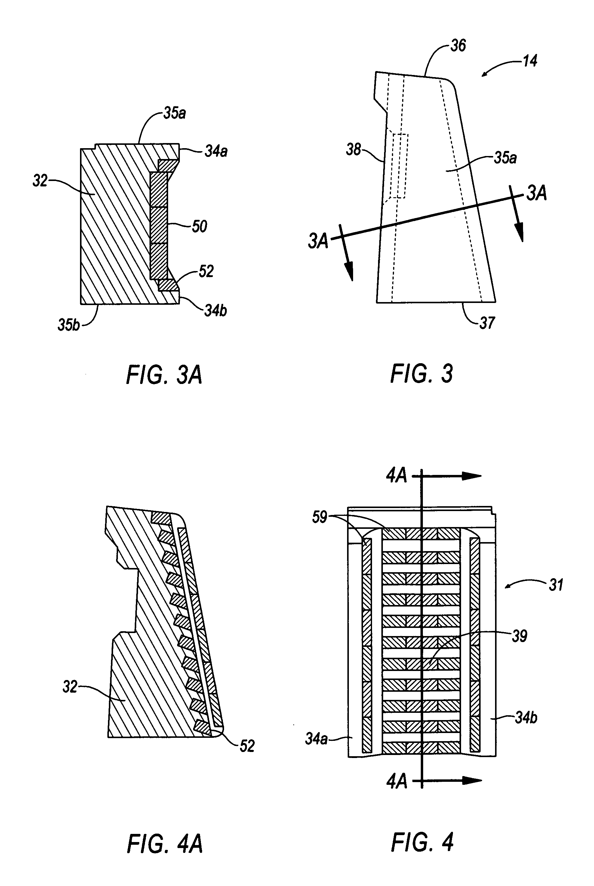
[0031]FIGS. 3, 3A, 4 and 4A disclose an impeller sho...


PUM

PropertyMeasurementUnit
angleaaaaaaaaaa
sizeaaaaaaaaaa
sizesaaaaaaaaaa

Abstract

The present invention is particularly, but not exclusively, useful for reducing wear of component parts of impact-type rock-crushing machines caused by earth aggregate flows during operation of impact crushers. The present invention includes a central feed body and impeller shoe that has hard material insert bars fixed therein to reduce wear. The exposed top surface of the central feed body and front face of the impeller shoe are impregnated with a plurality of cemented carbide insert bars. The cemented carbide insert bars form an upper composite matrix that helps to reduce wear and the premature wash out of the hard material insert bars integrally cast within the central feed body.

Description

BACKGROUND OF THE INVENTION[0001]Regardless of the precise nature or function of an apparatus in which components are subjected to wear by a material flow, wear causes need for repair and replacement of components and delays in use of the apparatus while one or more worn components are identified, inspected, removed, and replaced. Wear of components adds to the expense of maintaining and operating the apparatus.[0002]As a result of persistent wear caused by material flows, components on construction equipment exposed to material flow must be replaced. Replacement of components causes “down time” to repair, refit, and replace components. Additional expenses are associated with replacing the worn part or component, inventorying replacement components, and delivering a replacement component to what is often a remote site.[0003]For example, a wide variety of impact rock crushers are used in commerce to reduce the size of larger earth materials to smaller sized aggregate. The constructio...

Claims


Application Information

Patent Timeline
Patent Type & Authority Patents(United States)
IPC IPC(8): B02C19/00B02C13/18B02C13/28B22D19/02B22D19/06
CPCB02C13/1814B02C13/2804B22D19/06B22D19/02B02C2210/02
Inventor CONDON, GARY J.
Owner KENNAMETAL INC
Why Eureka
Try Eureka