Linear guide apparatus

a guide apparatus and linear technology, applied in the direction of brake systems, manufacturing tools, transportation and packaging, etc., can solve the problems of complex braking mechanism for enhancing vibration damping, inability to obtain desired damping capacity, and formation of gap between braking or damping member and guide rail, etc., to achieve high damping capacity

Inactive Publication Date: 2006-04-18
TOSHIBA MASCH CO LTD
View PDF30 Cites 27 Cited by
  • Summary
  • Abstract
  • Description
  • Claims
  • Application Information

AI Technical Summary

Benefits of technology

[0009]It is therefore an object of the present invention to solve the above-described problems in the prior art and provide a linear guide apparatus which, owing to the use of a gap-free braking device in a rolling guide, has a sufficiently high damping capacity.
[0010]In order to achieve the above object, the present invention provides a linear guide apparatus for guiding a linear motion of a movable body along a guide rail on a fixed structure in a machine tool, comprising: a rolling guide means including a rolling element for rolling on a surface of the guide rail; and a brake means for enhancing the damping capacity of the rolling guide section, wherein said brake section includes a pair of brake shoes, having a flexible structure, for sliding on the rolling element-rolling surface of the guide rail.
[0011]The brake section of the linear guide apparatus according to the present invention, unlike the conventional braking devices, has a flexible structure and does not have such a complicated mechanism or a hard structure that would form a gap between a brake shoe and a guide rail. The brake section can securely provide the linear guide apparatus with a sufficient damping capacity.

Problems solved by technology

Thus, sliding guides and rolling guides have advantages in terms of each other's disadvantages, and have disadvantages in terms of each other's advantages.
The conventional linear guide apparatuses thus utilize either a hydraulic pressure or air pressure to apply a load to a rail so as to generate a frictional force, which necessarily makes the braking mechanism for enhancing vibration damping complicated.
Further, with such a breaking mechanism, a gap may be formed between a braking or damping member and a guide rail.
The presence of even a very small gap causes an uncontrollable minute displacement of the braking or damping member in the gap direction, whereby the desired damping capacity cannot be obtained.

Method used


Image

  • Linear guide apparatus
  • Linear guide apparatus
  • Linear guide apparatus

Examples


first embodiment

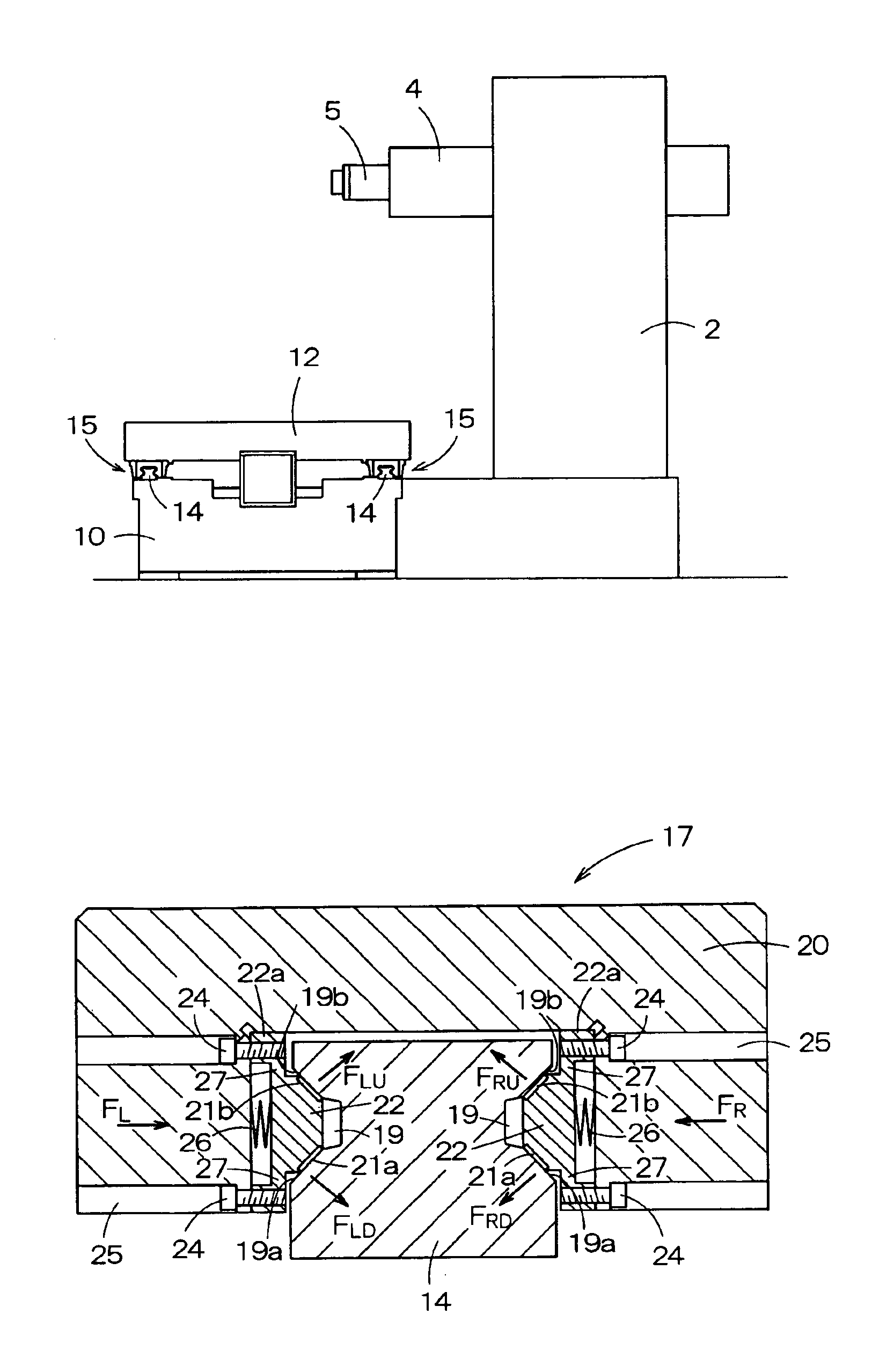
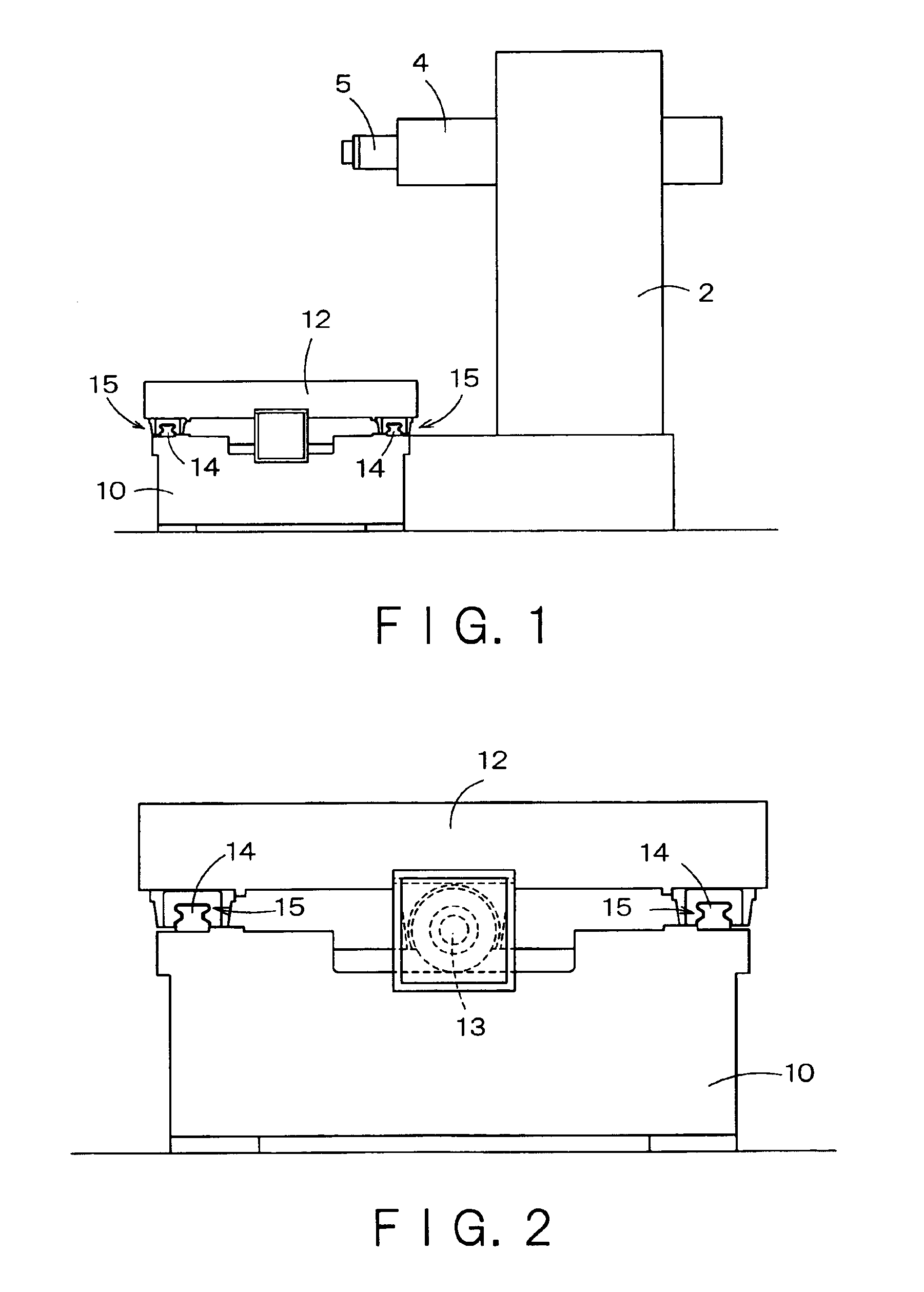
[0025]FIG. 2 shows, together with a table, a linear guide apparatus according to the present invention as viewed from the front in the moving direction of the table. This embodiment relates to application to a roller-type rolling guide for guiding a table in a machine tool.

[0026]In FIG. 2, the reference numeral 10 designates a bed and 12 designates the table. A ball screw 13, constituting a feed mechanism for the table 12, is provided on the upper surface of the bed 10. A pair of guide rails 14, disposed on either side of the ball screw 13, is laid in parallel with the axial direction of the ball screw 13. Guide units 15, each constituting the linear guide apparatus of this embodiment, are mounted to the lower surface of the table 12 each in engagement with the guide rail 14.

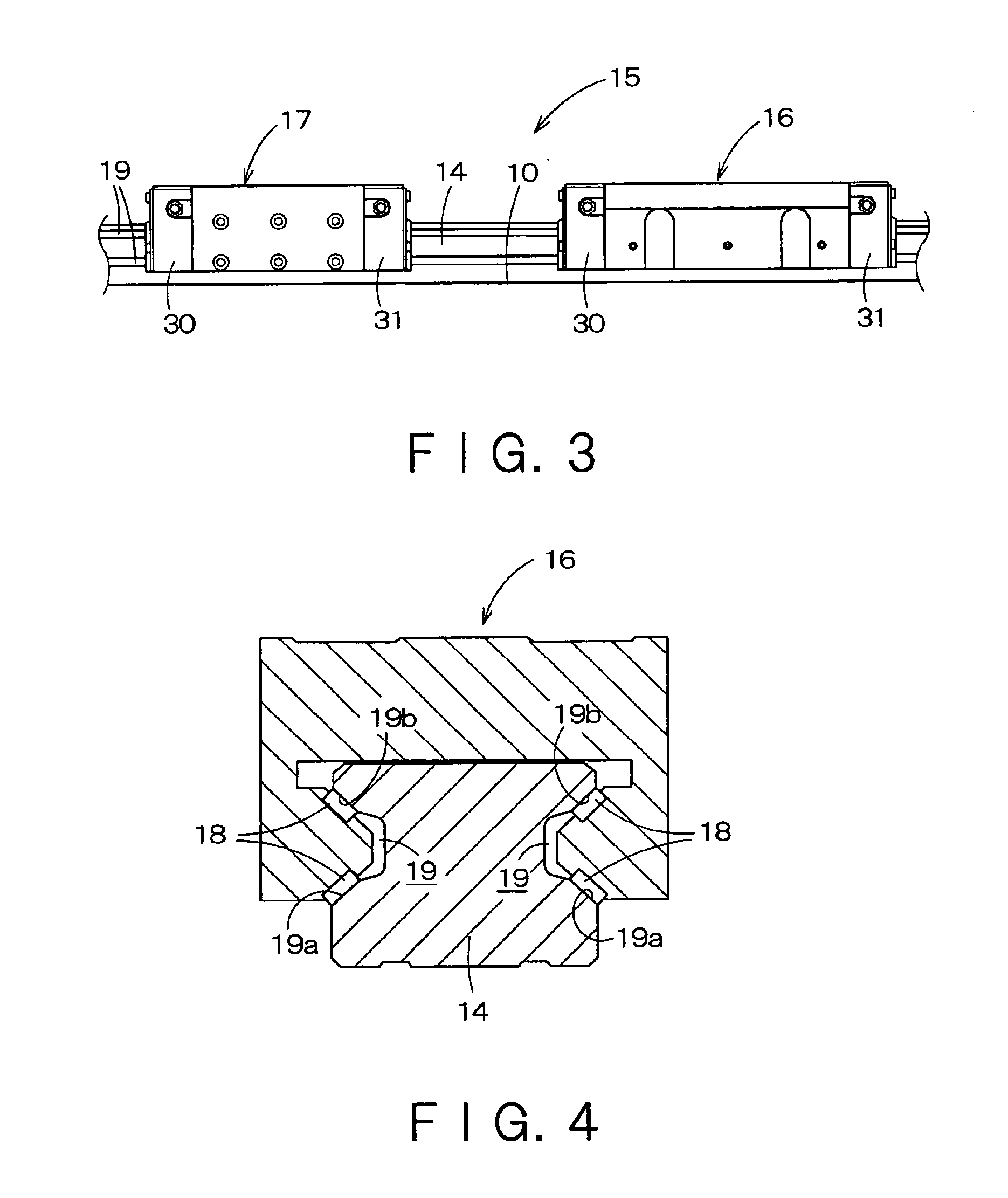
[0027]FIG. 3 is a side view of the linear guide apparatus of this embodiment.

[0028]As shown in FIG. 3, each guide unit 15 comprises a rolling guide section 16 and a brake section 17, disposed on the guide rail 1...

third embodiment

[0053] having the above construction, the pressing force can be adjusted in the following manner: As the pressing force adjustment bolt 42 is screwed and advanced in the screw hole 42, the compression spring 26 is increasingly compressed, whereby the pressing force of the compression spring 26, acting on the brake shoe 22 to press it against the roller-rolling surfaces 19a, 19b of the guide rail 14, increases accordingly, whereas the pressing force decreases as the pressing force adjustment bolt 42 is moved back in the opposite direction. Accordingly, by adjusting the screwing degree of each pressing force adjustment bolt 42 and fastening the lock nut 43 to fix the screwing degree, the pressing force of the brake shoe 22 as a whole can be distributed evenly over the roller-rolling surfaces 19a, 19b.

[0054]The fourth embodiment, shown in FIG. 8, relates to application of the preceding embodiment, i.e. the embodiment using the pressing force adjustment bolts 42 for evenly distributing...

fourth embodiment

[0055] the pressing force of the brake shoe 22 can be distributed evenly over the ball-rolling surface of the guide groove 33.

[0056]While the linear guide apparatus of the present invention has been described with reference to the preferred embodiments which relate to application as a guide for a table of a machine tool, the present invention can also be applied to various other movable bodies of a machine tool, such as a spindle head, a saddle, a cross rail, etc.

[0057]As described hereinabove, the brake section of the linear guide apparatus according to the present invention, unlike the conventional braking devices, utilizes an elastic member as a biasing means, has a flexible structure, and does not have a complicated mechanism or a hard structure that could form a gap between a brake shoe and a guide rail. The addition of such a gap-free braking device to a conventional rolling guide can provide a sufficient damping capacity to the linear guide apparatus.


PUM

PropertyMeasurementUnit
angleaaaaaaaaaa
lengthaaaaaaaaaa
widthaaaaaaaaaa

Abstract

There is provided a linear guide apparatus which, owing to the use of a gap-free braking device in a rolling guide, has a sufficiently high damping capacity. The linear guide apparatus for guiding a linear motion of a movable body along a guide rail on a fixed structure in a machine tool, includes: a rolling guide section including a rolling element for rolling on a rolling element-rolling surface of the guide rail; and a brake section for enhancing the damping capacity of the rolling guide section, the brake section including a pair of brake shoes, having a flexible structure, for sliding on the rolling element-rolling surface of the guide rail.

Description

BACKGROUND OF THE INVENTION[0001]1. Field of the Invention[0002]This invention relates to a linear guide apparatus for guiding a movable body, such as a table, in a machine tool.[0003]2. Description of the Related Art[0004]In machine tools, sliding guides and rolling guides are primarily employed in guide mechanisms for movable bodies, such as columns, spindle heads, tables, etc.[0005]Sliding guides, in which a sliding member makes a sliding contact with a guide surface, have a high static rigidity and, as compared to rolling guides, are excellent in damping of vibrations that could cause fluttering.[0006]On the other hand, rolling guides, which utilize a rolling contact between a rolling member and a guide surface, have a low vibration damping capacity. Because of low frictional force, however, rolling guides are superior in high speed and motion accuracy to sliding guides. Thus, sliding guides and rolling guides have advantages in terms of each other's disadvantages, and have disa...

Claims


Application Information

Patent Timeline
Patent Type & Authority Patents(United States)
IPC IPC(8): B23C9/00B23Q1/26B23Q1/40F16C29/10F16C29/12F16C32/00B23Q1/28F16C29/00
CPCB23Q1/28F16C29/00F16C29/10F16C29/12Y10T408/76Y10T409/309912Y10T409/304312Y10T408/91F16C2322/39
Inventor SHIBA, KAZUHIROKAI, YOSHIAKIDATE, TAKAO
Owner TOSHIBA MASCH CO LTD
Why Eureka
Try Eureka