
Data storage device with mechanism to control rotation of spindle motor

a technology of a data storage device and a rotational control, which is applied in the direction of magnetic recording, magnetic recording, bearings, etc., can solve the problems of increasing the complexity of the manufacturing process, and achieve the effect of effectively controlling the spindle motor and effective secure the spindle motor

Inactive Publication Date: 2006-04-18
HITACHI GLOBAL STORAGE TECH NETHERLANDS BV
View PDF9 Cites 19 Cited by
  • Summary
  • Abstract
  • Description
  • Claims
  • Application Information

AI Technical Summary

Benefits of technology

This solution effectively controls the floating of the rotor, simplifies the manufacturing process, and enhances the efficiency of the fluid dynamic bearing motor in hard disk drives, enabling a thinner design and improved performance.

Problems solved by technology

Accordingly, a fixing area of the base 702, to which the bias plate 713 is fixed, is required to be formed by cutting after casting, which makes the manufacturing process more and more complicated.

Method used


Image

  • Data storage device with mechanism to control rotation of spindle motor
  • Data storage device with mechanism to control rotation of spindle motor
  • Data storage device with mechanism to control rotation of spindle motor

Examples


Embodiment Construction

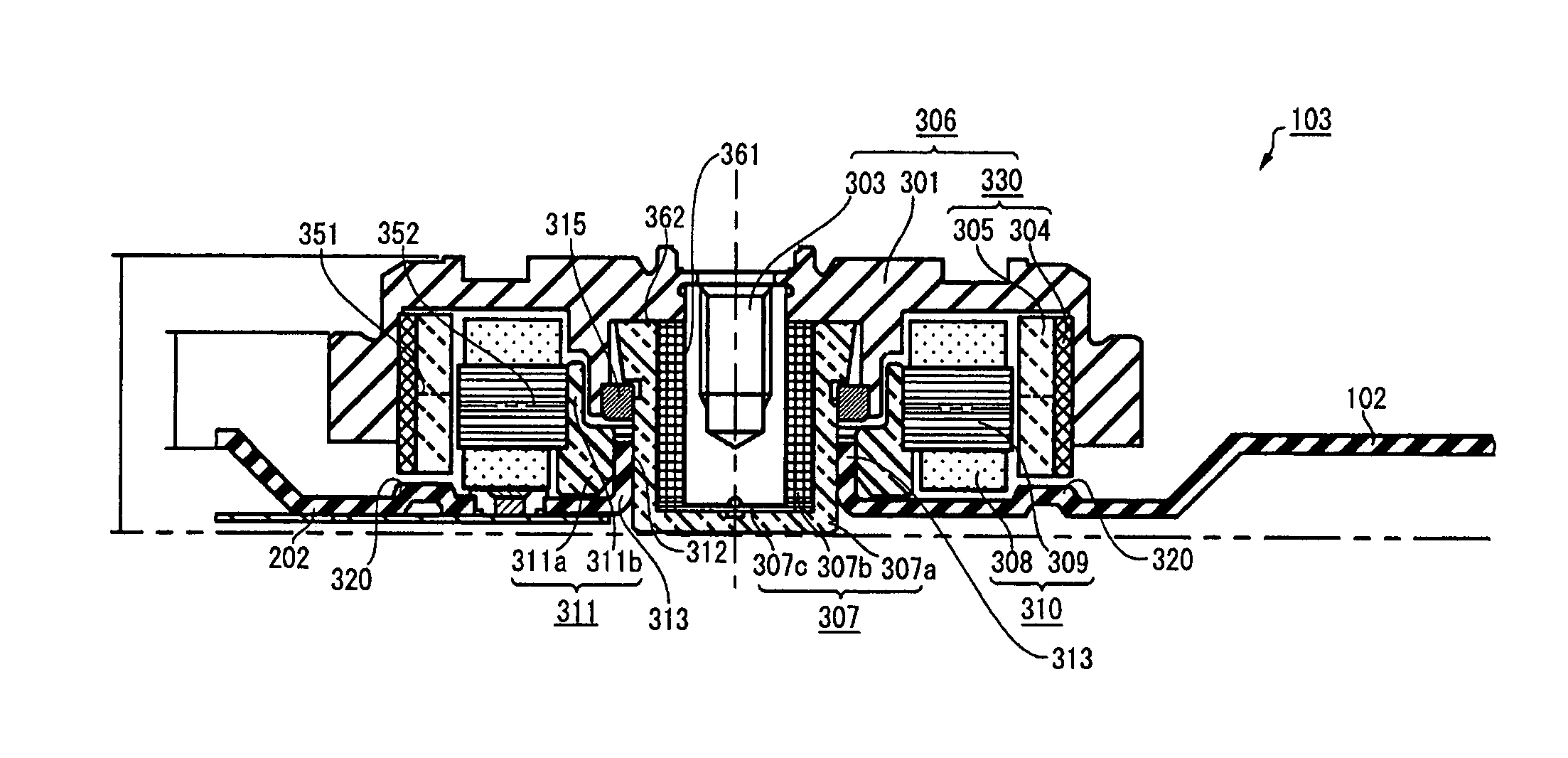
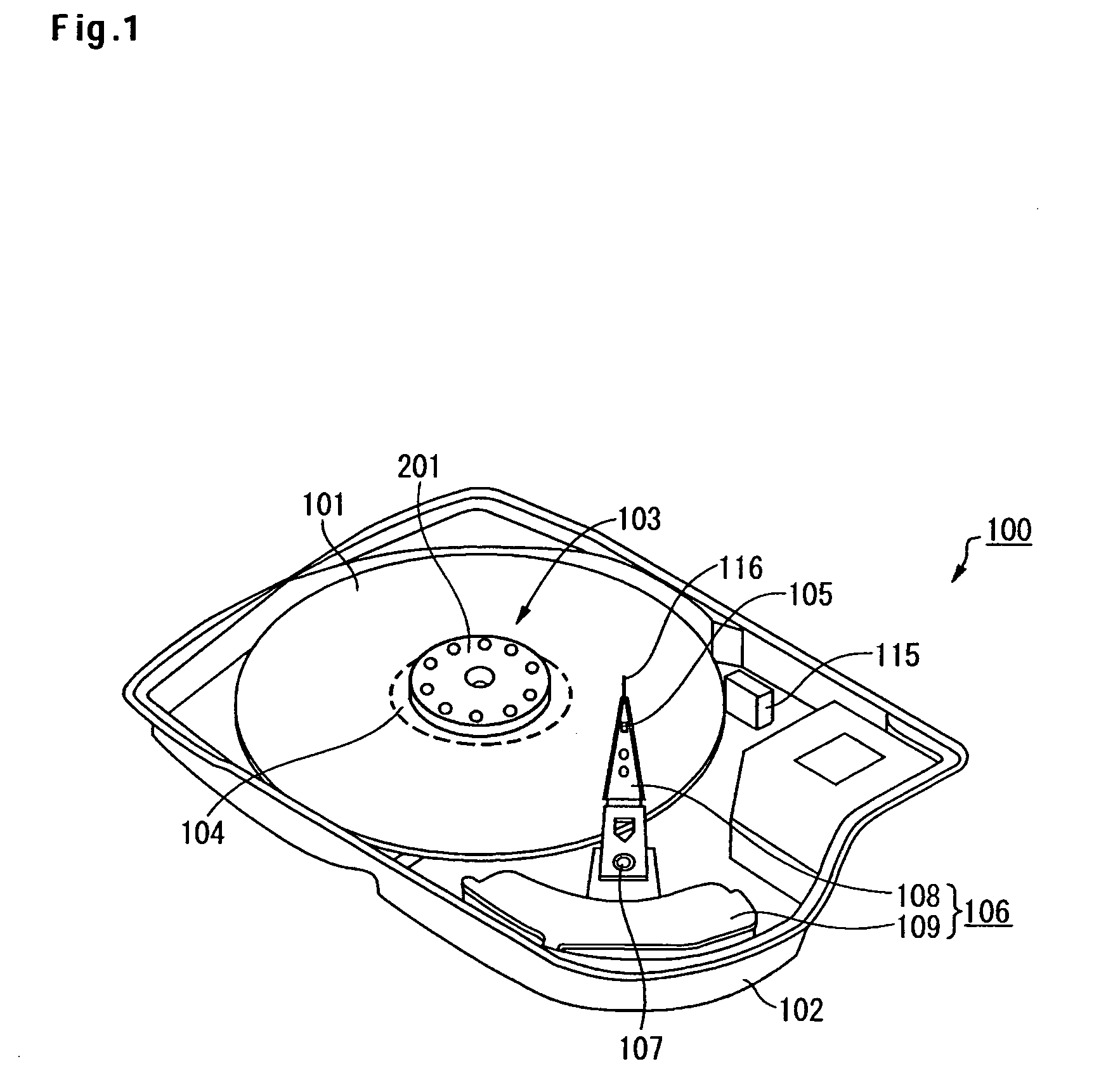
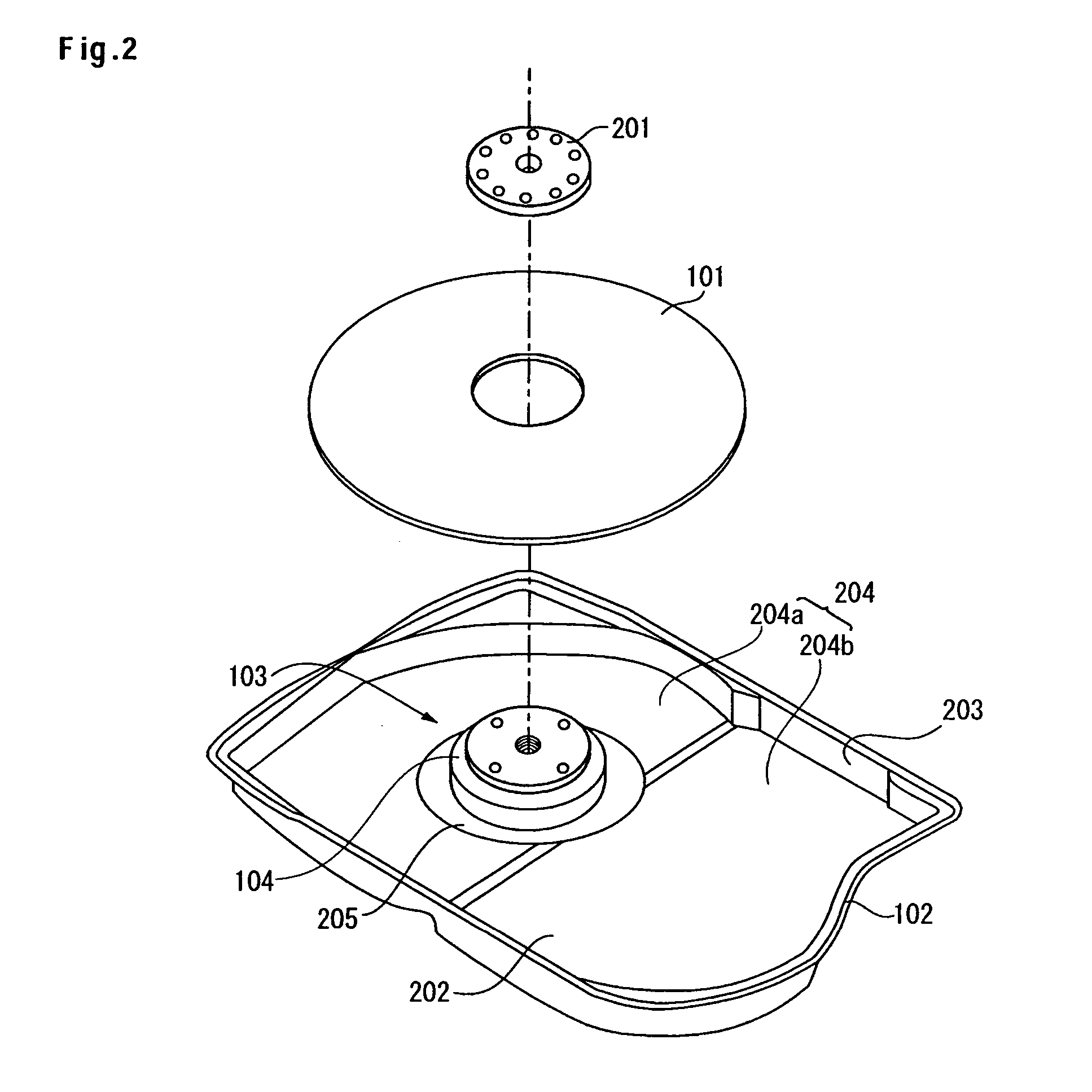
[0031]Embodiments to which the present invention can be applied will be described as below. The description given below is used to explain the embodiments of the present invention. The present invention, therefore, is not limited to the embodiments described below. For the sake of clarification of the description, the description and the drawings, which are disclosed hereinafter, shall be properly abbreviated, omitted, and simplified. In addition, a person skilled in the art can easily change, add, or convert each element of the embodiments within the scope of the present invention. Incidentally, in each of the drawings, the same elements are designated by similar reference numerals. Therefore, for the sake of clarification of the description, duplicated description will be omitted.

[0032]FIG. 1 is a perspective view schematically illustrating a configuration of a hard disk drive 100 according to this embodiment. In FIG. 1, reference numeral 101 denotes a magnetic disk, which is a no...


PUM

PropertyMeasurementUnit
rotating magnetic forceaaaaaaaaaa
pressureaaaaaaaaaa
shapeaaaaaaaaaa

Abstract

Embodiments of the present invention effectively control, by a simple structure, floating of a rotor of a fluid dynamic bearing motor mounted in a hard disk drive. In one embodiment, a base is formed of a magnetic material. The attractive force caused by the magnetic force acts between a bottom of the base and a magnet unit that is constituted of a rotor magnet and a back yoke. This makes it possible to attract a rotor to the base against the buoyant force produced by a thrust bearing, and thereby to effectively control the rotation of the rotor. On the bottom of the base, at a position facing the magnet unit, a convex part protruding from the inner surface of the base is formed in a ring-shape. Adjusting the height, or the width, of the convex part makes it possible to control the magnetic back pressure applied to the rotor.

Description

CROSS-REFERENCES TO RELATED APPLICATIONS[0001]This application claims priority from Japanese Patent Application No. JP2003-429317, filed Dec. 25, 2003, the entire disclosure of which is incorporated herein by reference.BACKGROUND OF THE INVENTION[0002]The present invention relates to a data storage device, and more particularly to a data storage device suitable for a hard disk drive.[0003]As a data storage device, various devices each using a medium are known—there are various kinds of media such as an optical disk and a magnetic tape. Among them, a hard disk drive has achieved widespread use as a storage device of a computer, serving as one of the indispensable storage devices for current computer systems. In addition, the superior characteristics of the hard disk drive are more and more widening the use of the hard disk drive; more specifically, the hard disk drive is applied not only to the computer systems, but also to, for example, a moving image recorder / player, a car navigati...

Claims


Application Information

Patent Timeline
Patent Type & Authority Patents(United States)
IPC IPC(8): H02K5/24H02K11/00H02K5/16H02K7/00F16C17/10G11B19/20H02K7/08H02K7/09H02K21/22
CPCH02K5/1675H02K7/09
Inventor TSUDA, SHINGOOHTA, MUTSUROKITAHORI, HIROKIOKASAKA, KAZUTAKA
Owner HITACHI GLOBAL STORAGE TECH NETHERLANDS BV
Learn More