Printing apparatus and its control method, and expendable attached to printing apparatus and having memory

a printing apparatus and control method technology, applied in the direction of recording apparatus, digital output to print units, instruments, etc., can solve problems such as increasing system costs

Inactive Publication Date: 2006-04-18
CANON KK
View PDF18 Cites 32 Cited by
  • Summary
  • Abstract
  • Description
  • Claims
  • Application Information

AI Technical Summary

Benefits of technology

[0013]The present invention has been made in consideration of the above problems, and has as its object to provide a printing apparatus and its control method, which control to inhibit any inadvertent write to a memory in an expendable so as to securely manage the exchange timing and the like of the expendable, and an expendable attached to the printing apparatus and having a memory.

Problems solved by technology

However, the method of storing important data upon controlling the printer engine, e.g., data that pertains to the service life of the cartridge, at a plurality of address positions, the nonvolatile memory requires a large capacity and will result in an increase in cost of the system.

Method used


Image

  • Printing apparatus and its control method, and expendable attached to printing apparatus and having memory
  • Printing apparatus and its control method, and expendable attached to printing apparatus and having memory
  • Printing apparatus and its control method, and expendable attached to printing apparatus and having memory

Examples


first embodiment

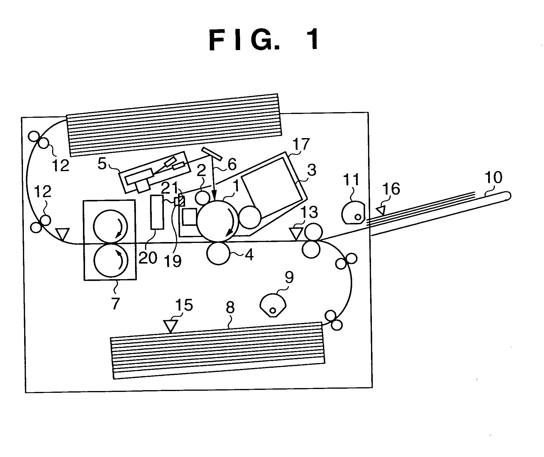
[0032]FIG. 1 is a sectional view showing the structure of a printing apparatus according to an embodiment of the present invention.

[0033]The same reference numerals in FIG. 1 denote substantially the same parts as in FIG. 9 described previously, and respective building components are as follows.

[0034]Reference numeral 1 denotes a photosensitive drum for forming an electrostatic latent image; 2, a charging roller for uniformly charging the photosensitive drum 1; 5, an optical unit for scanning a laser beam on the surface of photosensitive drum 1; 6, a laser beam emitted by the optical unit 5; 3, a developer for developing an electrostatic latent image formed on the photosensitive drum 1 by toner; 4, a transfer roller charger for transferring a toner image on the photosensitive drum 1 onto a predetermined paper sheet; 7, a fixing device for melting and fixing toner on the paper sheet; 8, a standard cassette for storing a stack of paper sheets used in a print process; 9, a standard cas...

modified example

[0053]The lock functional unit 21a of the nonvolatile memory 21 in the toner cartridge 17 can be implemented by the aforementioned appropriate gate circuit, but they can also be implemented by a processor using software. Also, an example of the arrangement and processing sequence in such case will be explained below.

[0054]The lock functional unit 21a is implemented by a processor 120, as shown in FIG. 12. The processor 120 comprises a program memory (ROM and RAM) which stores a program of that operation process, and is also used as a simple work memory. The processor 120 is connected to the memory element 21b of the nonvolatile memory 21 via an 8-bit bus and 3-bit address bus, and read and write signal lines are connected therebetween.

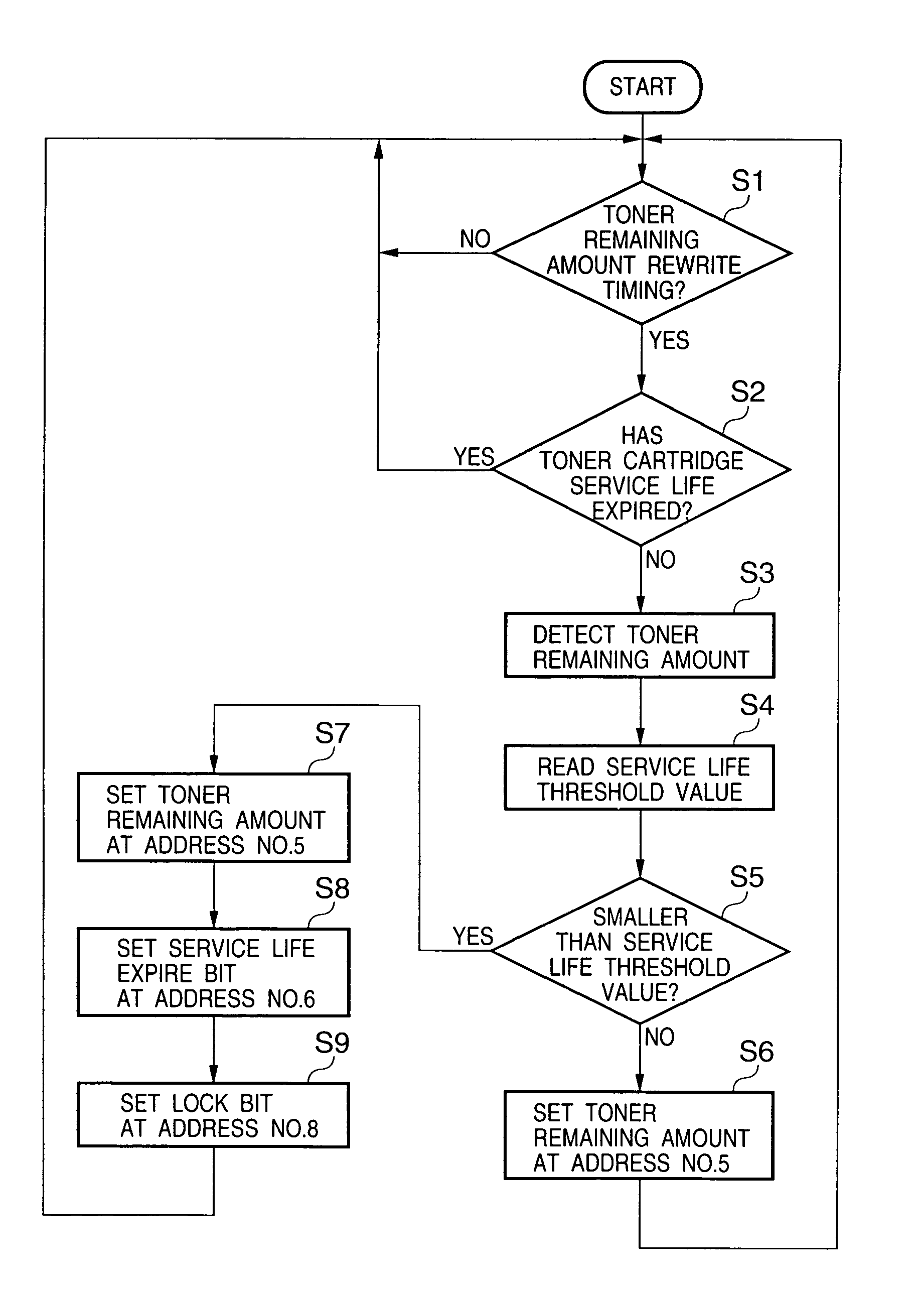
[0055]The operation process sequence of the processor 120 will be explained below with reference to the flow chart in FIG. 13. A power supply required for operating the processor 120 uses a Vcc signal from the printer control unit.

[0056]In step S11, th...

second embodiment

[0060]The second embodiment will explain a case wherein a wireless communication function is used between the nonvolatile memory 21 and printer control unit 20.

[0061]FIG. 6 shows the interface between the printer control unit 20 and a wireless memory.

[0062]Toner level detection is done in the same manner as in the first embodiment.

[0063]In the second embodiment, the interface between the nonvolatile memory 21 and printer control unit 20 has a wireless arrangement, i.e., has no electrical contacts. For this reason, the read / write driver circuit 20a is mounted in the printer control unit 20 and it is connected to the coil antenna 20b. The cartridge has an antenna 21b in coil-shape, which is connected to the nonvolatile memory 21 and is located at a position opposite to the antenna 20b when attaching to the printer. The communication is established by electromagnetical coupling between antenna 20b and 21b.

[0064]In principle, magnetic field generated by flowing a predetermined modulate...


PUM


Abstract

This invention provides a printing apparatus which controls to inhibit any inadvertent write to a memory in an expendable so as to securely manage the exchange timing and the like of the expendable. For this purpose, the expendable such as a toner cartridge or the like comprises a rewritable nonvolatile memory (21) which holds information indicating whether or not its service life has expired. When the toner cartridge is attached to the printing apparatus, it is ready to communicate with a printer engine controller in the printing apparatus, and write to the nonvolatile memory (21) can be made in accordance with an instruction from a control unit. A lock functional unit (21a) writes information indicating write inhibition at a predetermined address in the nonvolatile memory (21), thus inhibiting write to the address position that stores the information indicating whether or not its service life has expired.

Description

FIELD OF THE INVENTION[0001]The present invention relates to a printing apparatus and its control method, and an expendable attached to the printing apparatus and having a memory.BACKGROUND OF THE INVENTION[0002]FIG. 9 shows the arrangement of a conventional electrophotographic as an example of a printing apparatus of this type.[0003]Referring to FIG. 9, reference numeral 1 denotes a photosensitive drum for forming an electrostatic latent image; 2, a charging roller for uniformly charging the photosensitive drum 1; 5, an optical unit for generating a laser beam which scans the surface of photosensitive drum 1 upon exposure; 6, a laser beam emitted by the optical unit 5; 3, a developer for developing an electrostatic latent image formed on the photosensitive drum 1, by toner; 4, a transfer roller charger for transferring a toner image on the photosensitive drum 1 onto a predetermined paper sheet; 7, a fixing device for melting and fixing toner on the paper sheet; 8, a standard casset...

Claims


Application Information

Patent Timeline
Patent Type & Authority Patents(United States)
IPC IPC(8): G06F13/00G03G21/00G03G15/00G03G21/18G06F3/12
CPCG03G21/1889G03G15/5079G03G15/556G03G15/553G03G2221/1823G03G2215/0888G03G21/00
Inventor SERIZAWA, YOJI
Owner CANON KK
Why Eureka
Try Eureka