Fixed phase clock and strobe signals in daisy chained chips

a technology of daisy chained chips and phase clocks, applied in the field of integrated circuit chips, can solve the problems of limiting the bandwidth over the bus channel, adding cost and power consumption to the system,

Inactive Publication Date: 2006-04-18
INTEL CORP
View PDF17 Cites 150 Cited by
  • Summary
  • Abstract
  • Description
  • Claims
  • Application Information

AI Technical Summary

Problems solved by technology

The multi-drop busses can have electrical discontinuities that generate distortion and limit the bandwidth over the bus channel.
However, these approaches may add cost and power consumption to the system.

Method used


Image

  • Fixed phase clock and strobe signals in daisy chained chips
  • Fixed phase clock and strobe signals in daisy chained chips
  • Fixed phase clock and strobe signals in daisy chained chips

Examples


Embodiment Construction

A. Overview

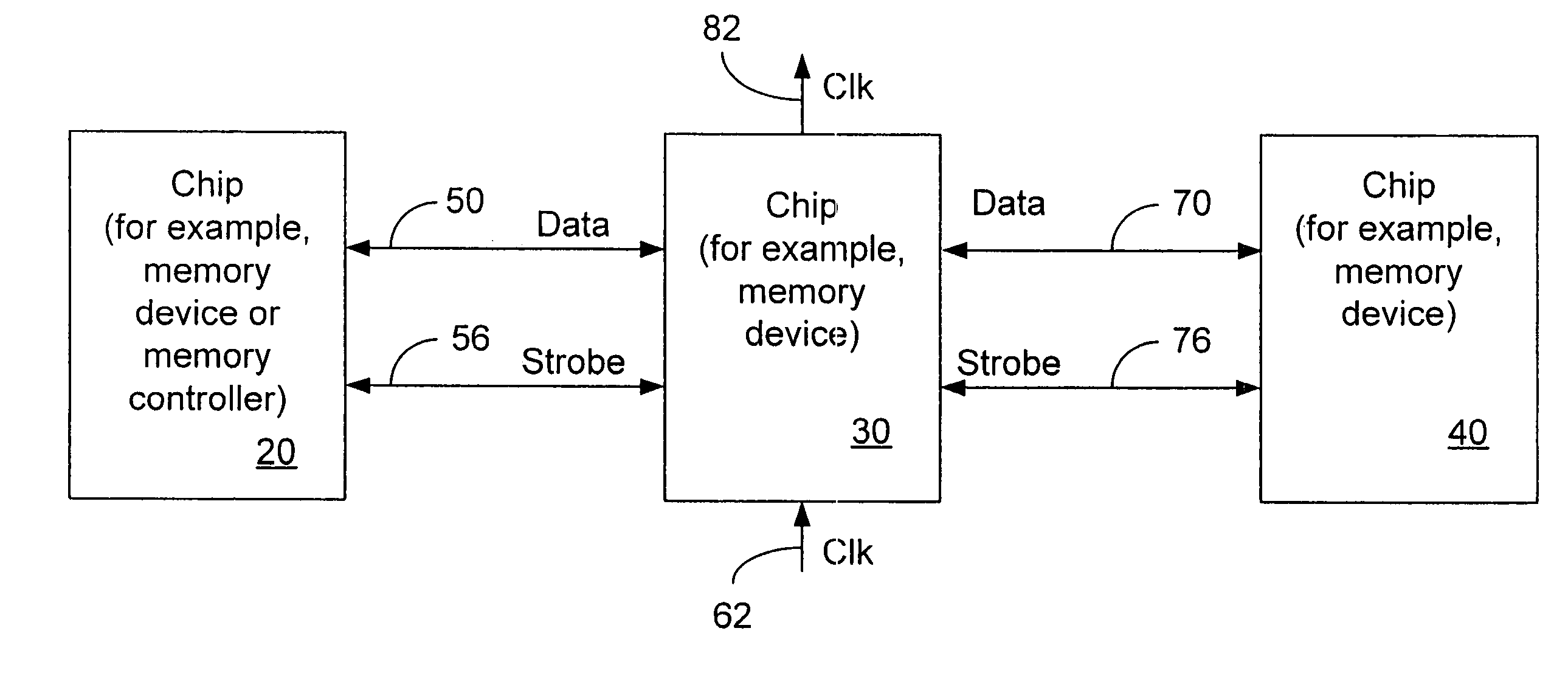
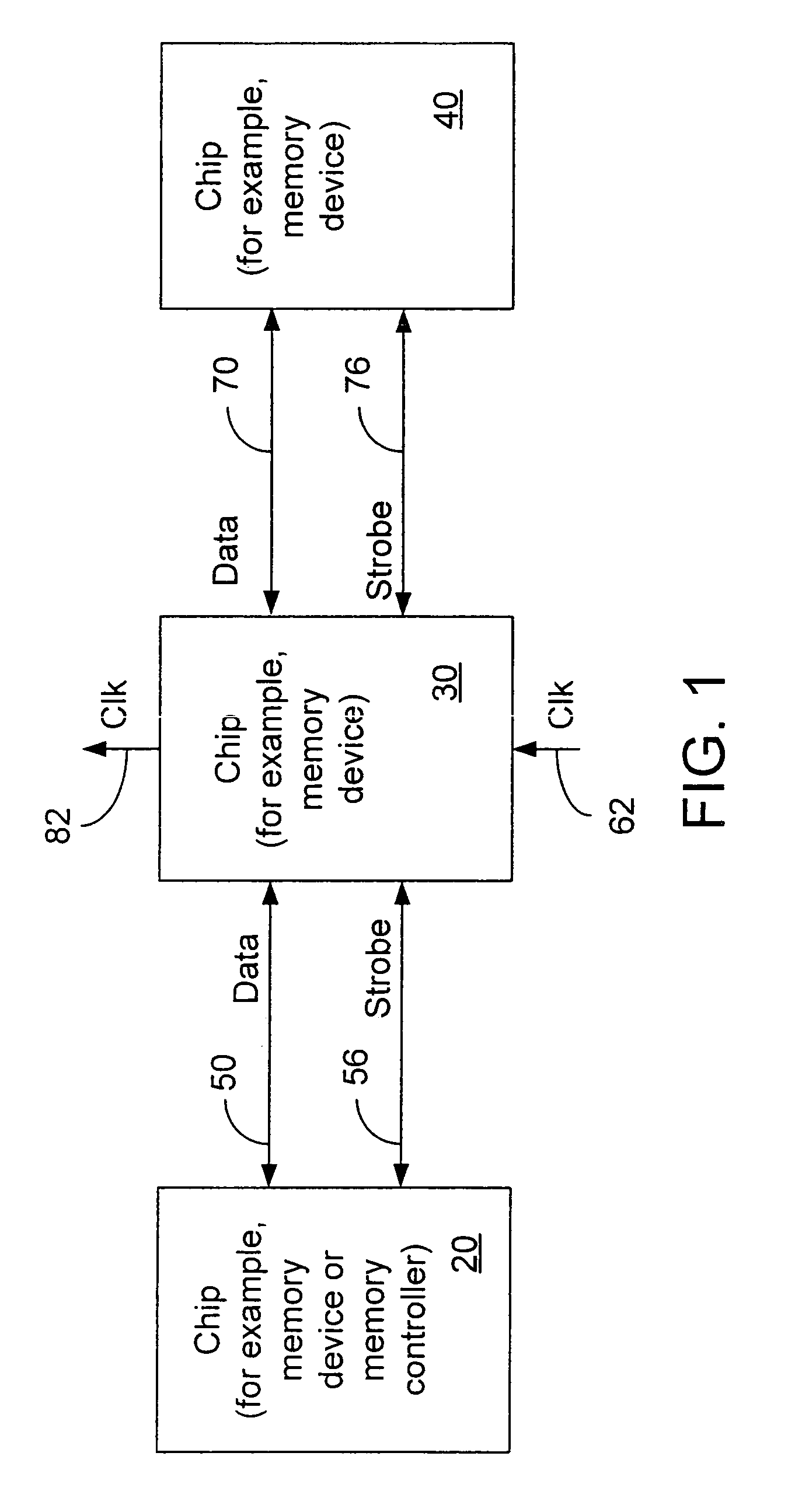
[0013]Referring to FIG. 1, a daisy chained, point to point system includes chips 20, 30, and 40. As an example, chip 20 may include a memory controller or be a memory device and chips 30 and 40 may be memory devices, although the chips may be other than memory controllers or memory devices. Chips 20 and 30 communicate with each other through at least data signals on conductors 50 and a first external strobe signal on conductor 56. Likewise, chips 30 and 40 communicate with each other through at least data signals on conductors 70 and a second external strobe signal on conductor 76. An external clock signal (clk) is passed from conductor(s) 62 to chip 30 to conductor(s) 82. The external clock signal may be the same clock signal as is used by chips 20 and / or 40 or a different clock signal. The data signal may be a traditional data signal with address and command signals being supplied separately, or the data signal may be a more generic signal that includes traditional data...


PUM


Abstract

In some embodiments, a chip includes first and second ports to provide first and second received data signals and first and second received strobe signal, respectively. An internal clock signal has a fixed phase relationship to the first received strobe signal and the second received strobe signal has an arbitrary phase relationship with the internal clock signal. First and second write blocks latch the first and second received data signals synchronously with the first and second received strobe signals, respectively. Other embodiments are described and claimed.

Description

BACKGROUNDTECHNICAL FIELD[0001]The present inventions relate to integrated circuit chips and, more particularly, to daisy chained chips including a strobe signal and clock signal with a fixed phase relationship.BACKGROUND ART[0002]A multi-drop bus is used to connect more than two chips to a set of conductors. Dynamic Random Access Memory (DRAM) devices have commonly been used with a multi-drop bus. The multi-drop busses can have electrical discontinuities that generate distortion and limit the bandwidth over the bus channel. For synchronous systems, a clock is distributed to each chip. The clock is usually distributed in a similar multi-drop fashion, limiting the bandwidth of the clock channel. One way to increase bandwidth of the clock channel is to drive multiple copies of the clock to a memory module (such as a dual in line memory module (DIMM)) to limit loading. Another approach is to put a phase locked loop (PLL) component on the DIMM and use this to drive a clock to the DRAM d...

Claims


Application Information

Patent Timeline
Patent Type & Authority Patents(United States)
IPC IPC(8): G11C7/00G11C8/00G04G99/00G06F13/16G11C7/10
CPCG11C7/10G11C7/1051G11C7/1093G11C7/1075G11C7/1078G11C7/1066G11C7/22
Inventor MOONEY, STEPHEN R.KENNEDY, JOSEPH T.
Owner INTEL CORP
Why Eureka
Try Eureka