Cluster analysis of genetic microarray images

a genetic microarray and cluster analysis technology, applied in image enhancement, library screening, instruments, etc., can solve the problems of varying the level of computational complexity required

Inactive Publication Date: 2006-04-18
BOARD OF RGT UNIV OF NEBRASKA
View PDF10 Cites 34 Cited by
  • Summary
  • Abstract
  • Description
  • Claims
  • Application Information

AI Technical Summary

Problems solved by technology

Both of these methods provide superior results compared to prior segmentation a

Method used


Image

  • Cluster analysis of genetic microarray images
  • Cluster analysis of genetic microarray images
  • Cluster analysis of genetic microarray images

Examples


Embodiment Construction

[0014]The following description sets forth the general procedures involved in practicing the present invention. To the extent that specific materials are mentioned, it is merely for purposes of illustration and is not intended to limit the invention. Unless otherwise specified, general hybridization procedures, such as those set forth in Current Protocols in Molecular Biology, Ausubel et al. eds., J W Wiley and Sons, NY (1998) and Molecular Cloning A Laboratory Manual, Second Edition, Sambrook et al. eds., Cold Spring Harbor Laboratory Press, 1989 are utilized.

Definitions

[0015]Various terms relating to the biological molecules of the present invention are used hereinabove and also throughout the specifications and claims.

[0016]“Nucleic acid” or a “nucleic acid molecule” as used herein refers to any DNA or RNA molecule, either single or double stranded and, if single stranded, the molecule of its complementary sequence in either linear or circular form. In discussing nucleic acid mol...


PUM

PropertyMeasurementUnit
Dispersion potentialaaaaaaaaaa
Ratioaaaaaaaaaa
Areaaaaaaaaaaa

Abstract

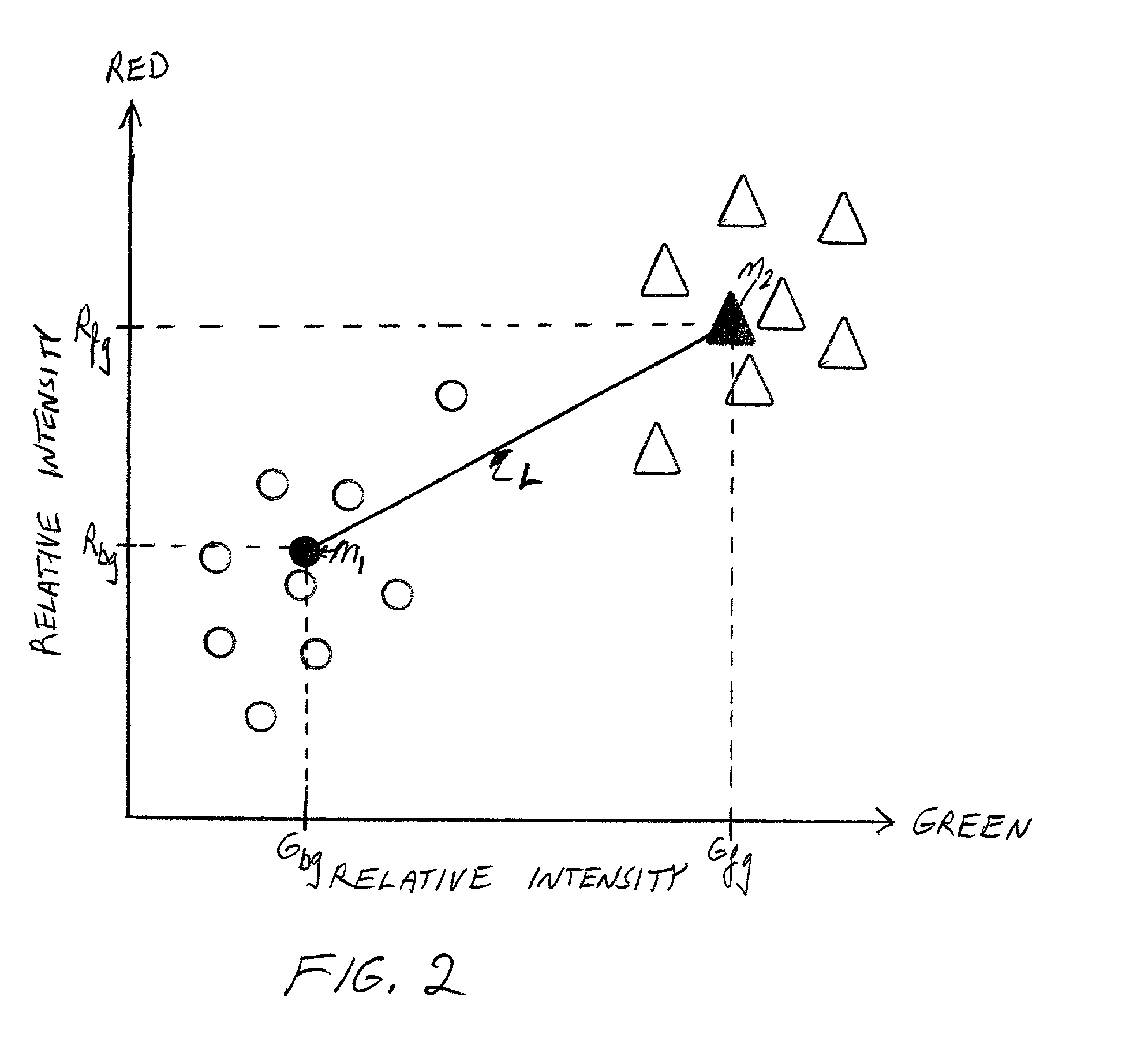
A method for determining relative incidence of a binding substance within two biological samples is provided. The two samples are labeled with luminescent materials having different chromatic properties. An image of the luminescent materials upon a binding site of a microarray is analyzed as two clusters of data points scattered about respective representative pairs of chromatic intensity values. The relative incidence of the binding substance is determined as a ratio of differences between corresponding indices of the representative pairs.

Description

FIELD OF THE INVENTION[0001]The present invention relates to an analysis technique for use in differential gene expression studies employing DNA microarrays. In particular, the present invention relates to the use of a clustering analysis method for determining the differential expression levels of targeted nucleic acid molecules based on relative intensities and intensity ratios of a plurality of detectably labeled hybridizing nucleic acid sequences. The methods of the present invention are also applicable to the analysis of DNA-protein, RNA-protein, and protein-protein interactions.BACKGROUND[0002]DNA microarrays are known in which genetic probes are affixed to a substrate at discrete locations for binding with a sample containing labeled genetic material. Terminologies that have been used in the literature to describe this technology include, biochip, DNA chip, DNA microarray and gene array. DNA microarrays are fabricated by high-speed robotics, generally on glass but sometimes o...

Claims


Application Information

Patent Timeline
IPC IPC(8): G06K9/00G01N33/48G06F7/00C12Q1/68C40B30/04G01N33/53G01N33/58G01N33/68G06F19/00G06T7/00G06T7/40G16B25/00
CPCC12Q1/6837C40B30/04G01N33/5308G01N33/582G01N33/6845G06F19/20G06T7/0012G06T7/408G06K9/00Y10S707/99943G06T2207/30072C12Q2565/102C12Q2537/161G06T7/90G16B25/00G06F18/00
Inventor BOZINOV, DANIELRAHNENFUHRER, JORG
Owner BOARD OF RGT UNIV OF NEBRASKA
Why Eureka
Try Eureka