
Optical pickup and optical information reproducing apparatus using same

a technology of optical information and pickup, applied in the field of optical pickup modules, can solve the problems of extremely impaired aberration correctability, limited light beams that are successfully correctable in wavefront aberration, and the aberration corrector device is faced, and achieves the effect of increasing usability

Inactive Publication Date: 2010-05-11
HITACHI MEDIA ELECTORONICS CO LTD
View PDF10 Cites 0 Cited by
  • Summary
  • Abstract
  • Description
  • Claims
  • Application Information

AI Technical Summary

Benefits of technology

"The invention provides an improved optical pickup with increased usability and an optical information reproduction apparatus using the pickup. This means that the optical pickup can be used more easily and efficiently in the optical information reproduction apparatus."

Problems solved by technology

Unfortunately, this aberration corrector device is faced with two major serious technical problems which follow.
In the prior art aberration corrector device, the light beam that is successfully correctable in its wavefront aberration is limited to a single kind.
Adversely this means that regarding a light beam having an effective beam diameter different from the effective beam diameter, its aberration correctability becomes extremely impaired even when performing aberration correction by an aberration correction device identical to the corrector device.
It is thus apparent that in the above-noted prior art aberration correction device, even when performing the optimum design of transparent electrodes in any possible way, it is impossible to achieve the optimum solution capable of obtaining excellent aberration correction performances for both of the two light beams that are different in effective beam diameter from each other.
However, as stated previously, the prior art fails to disclose the above-noted problems and any teachings as to the configuration capable of successfully correcting together wavefront aberrations of multiple kinds of light beams different in effective beam diameter from one another by use of a single aberration correction device.
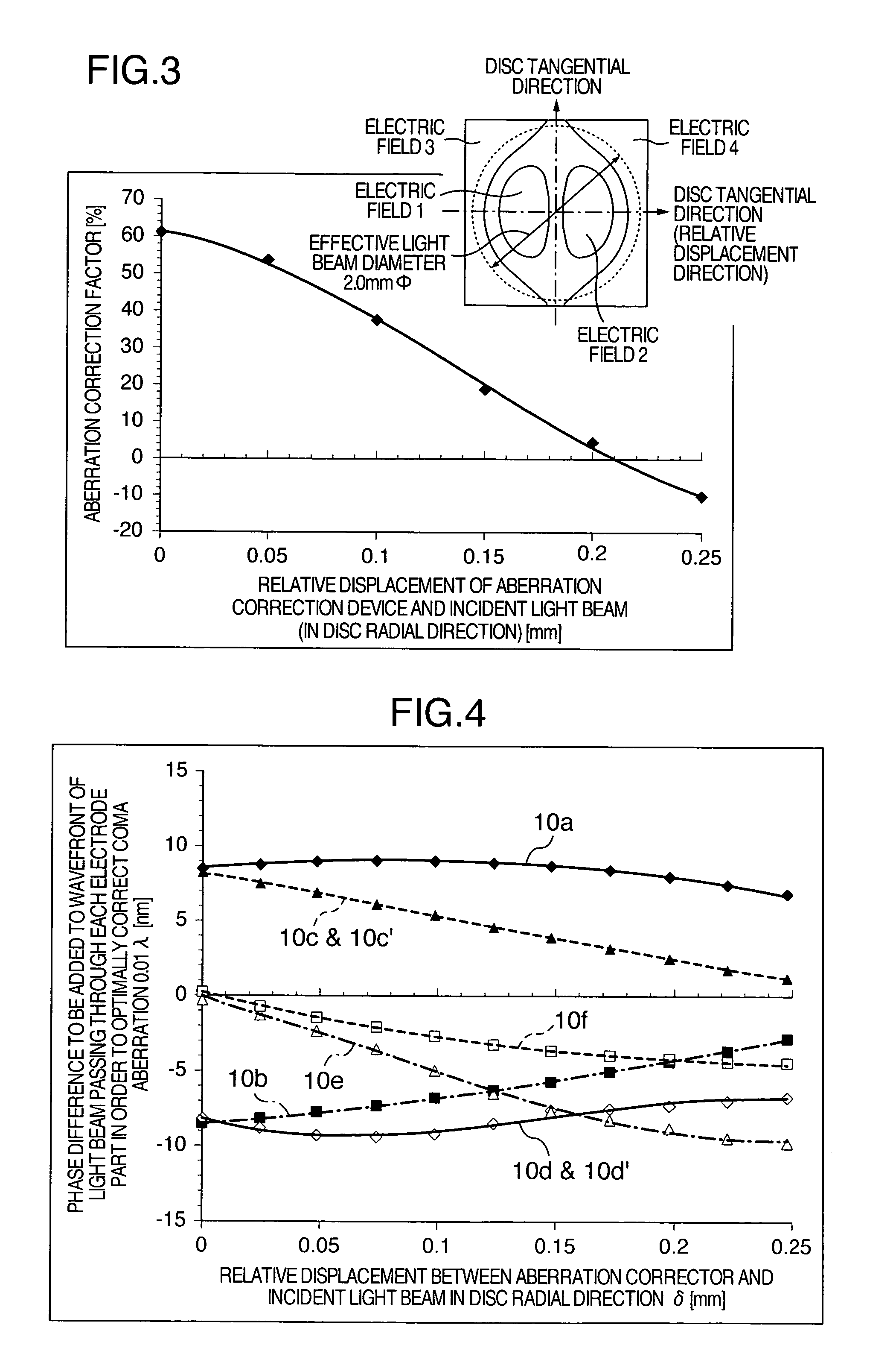
In addition to the above-noted first problem, the prior art aberration correction device suffers from a problem which follows: the creation of a relative position deviation or displacement between this aberration corrector device and a light beam falling thereonto would result in an appreciable decrease in aberration correcting performance.
However, in the actual optical pickup, it is unavoidable in any way that relative displacement of about several tens of μm occurs between the light beam and the aberration corrector device due to the presence of attachment position variations occurring during assembly of such pickup.
Accordingly, whether superior aberration correction performance is achievable even in the presence of such relative displacement is an important issue which affects the optical pickup's performances.
However, the prior art discloses neither the above-noted problems nor effective means for avoiding the reduction of aberration correction performance occurring due to relative displacement.

Method used


Image

  • Optical pickup and optical information reproducing apparatus using same
  • Optical pickup and optical information reproducing apparatus using same
  • Optical pickup and optical information reproducing apparatus using same

Examples


embodiment 1

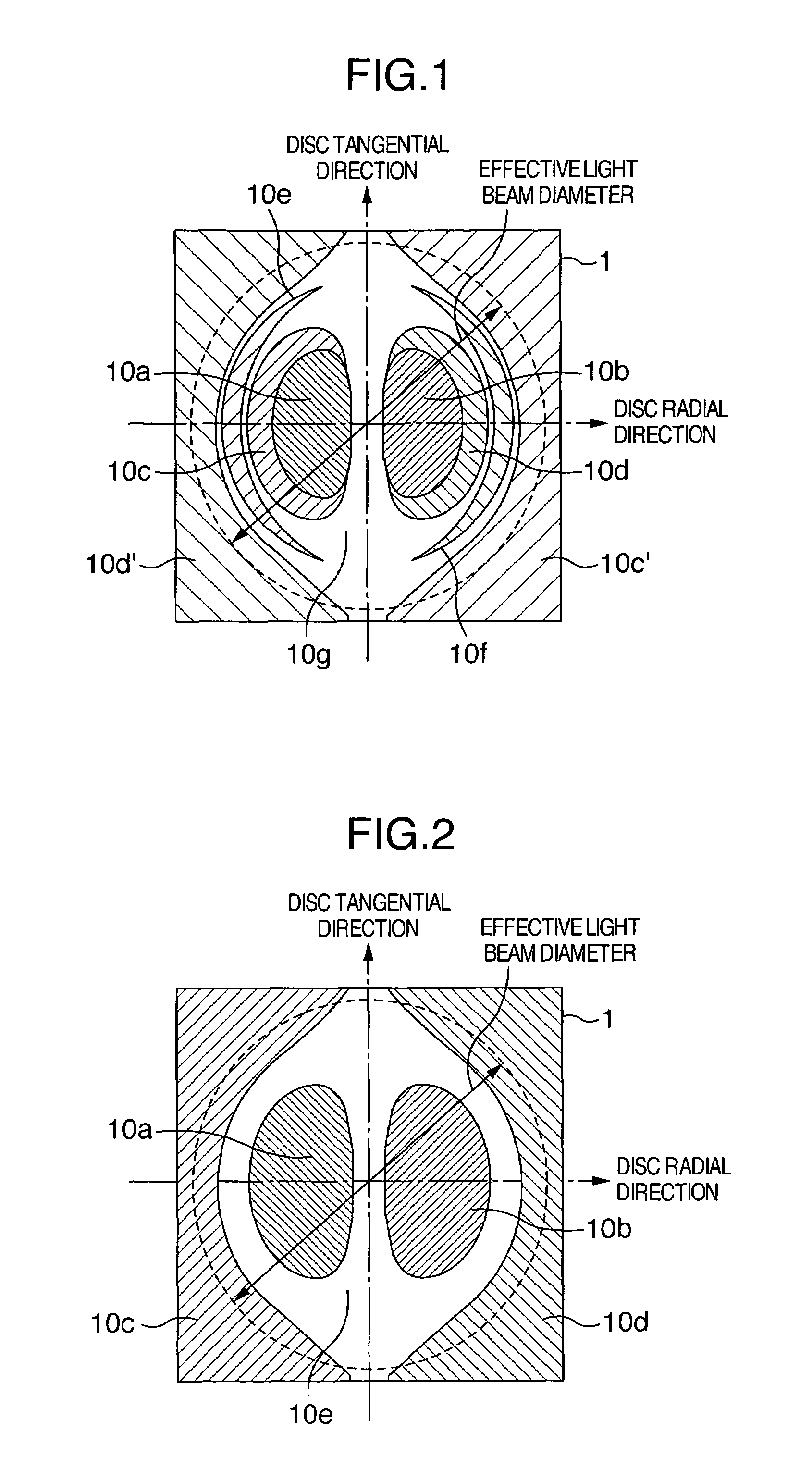
[0033]An embodiment 1 of this invention will be described with reference to FIG. 1, which shows an exemplary electrode pattern of a coma aberration correction device embodying the invention. Although the aberration corrector device of this embodiment is also arranged so that a predetermined electrode plane is provided in the form of interposing a liquid crystal (LC) element in a similar way to the prior art aberration corrector device, FIG. 1 is a diagram schematically showing a plan view of one example of each electrode pattern as provided on such the electrode plane. Note that in this diagram, its lateral axis direction corresponds to a radial direction of an optical disc whereas the vertical axis direction is equivalent to a tangential direction of the disc, wherein the electrode pattern as shown herein has its function of correcting coma aberration occurring in the lateral axis direction, i.e., the disc radial direction.

[0034]As shown in FIG. 1, transparent electrodes 10a and 10...

embodiment 2

[0042]A second embodiment of this invention will be described with reference to FIGS. 4 and 5. When actually incorporating an aberration correction device into an optical pickup, it sometimes happens that relative position deviation or displacement takes place between the aberration corrector device and a light beam as guided to enter this device due to the presence of several factors, such as the accuracy of its constituent components and variations during assembly. However, as shown by the above-stated example of FIG. 3, the prior art aberration corrector device is such that the aberration correction factor—i.e., this aberration corrector device's own aberration correction performance—drastically decreases due to such relative displacement. Even in this case also, by using this embodiment and adjusting the voltage being applied to each electrode in accordance with a relative displacement amount and also controlling at a prespecified value a relative phase difference being added to...

embodiment 3

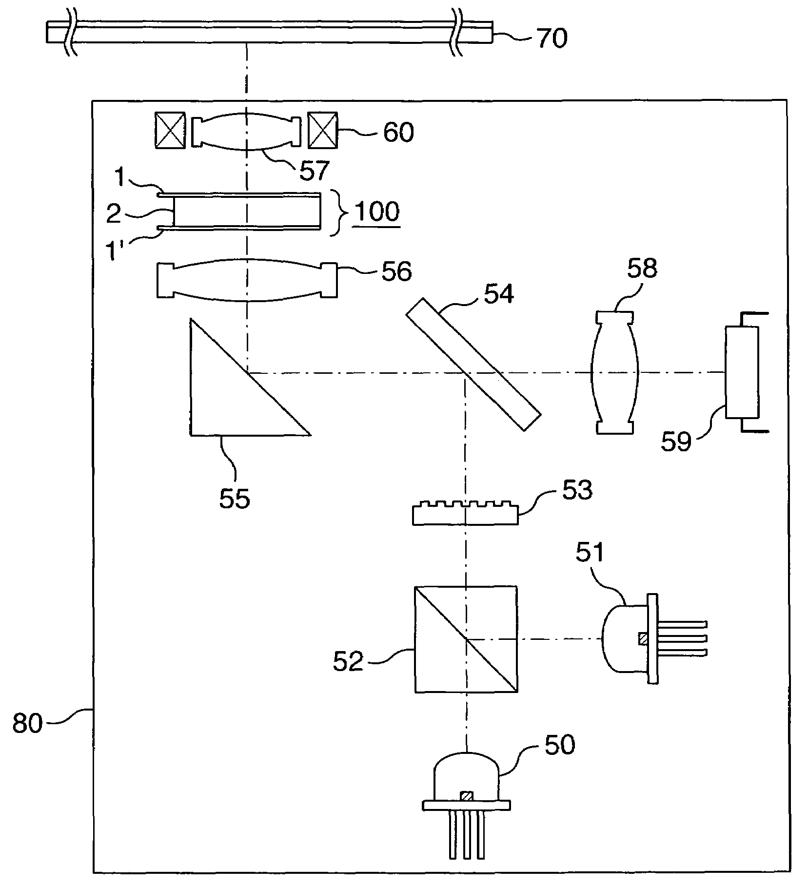
[0048]Referring to FIG. 6, one example is shown of an optical pickup mounting therein the aberration correction device as described in the first and second embodiments.

[0049]Within an optical system 80 of the pickup as surrounded by solid lines in FIG. 6, a semiconductor laser light source 50 for outward irradiation of a beam of DVD-use laser light having a wavelength of from 650 to 660 nm and a semiconductor laser light source 51 for emission of a beam of CD-use laser light having its wavelength in a range of 780 to 790 nm are disposed. These laser beams as emitted from respective semiconductor laser light sources are combined together by a light beam-combining prism 52 into the same light path and then guided to enter a half mirror 54, also known as “semi-transparent” mirror, through a diffraction grating 53. Each laser beam reflected from the half mirror 54 travels via a rise-up mirror 55 to reach a coupling lens 56. By this coupler lens 56, the beam is converted into a substanti...


PUM

PropertyMeasurementUnit
diameteraaaaaaaaaa
diameteraaaaaaaaaa
effective diameteraaaaaaaaaa

Abstract

An optical pickup module with enhanced aberration correctability is disclosed. This pickup includes more than two different types of laser light sources, an objective lens for collecting and focusing any one of the laser beams leaving the light sources onto an optical disc, and an aberration correction device of the liquid crystal (LC) type, which is disposed between the light sources and the objective lens. The aberration corrector has a surface on which multiple spaced-apart electrodes are patterned for enabling aberration correction relative to incident beams. The corrector controls the potential of a voltage being applied to each electrode in deference to incident beam properties and variations occurrable thereto, e.g., wavelength, effective beam diameter and relative incidence position offsets, thereby to optimally correct beam aberrations, such as coma aberration or wavefront aberration. An optical information reproduction apparatus using the pickup is also disclosed.

Description

INCORPORATION BY REFERENCE[0001]The present application claims priority from Japanese application JP2005-371301 filed on Dec. 26, 2005, the content of which is hereby incorporated by reference into this application.BACKGROUND OF THE INVENTION[0002]1. Field of the Invention[0003]The present invention relates to an optical pickup module with aberration correctability and an optical information reproduction apparatus using the pickup.[0004]2. Description of Related Art[0005]A background art in this technical field is disclosed, for example, in JP-A-11-110802. This Japanese bulletin contains, as an objective of the invention disclosed therein, the recitation which reads as follows: “ . . . provide an aberration correcting device capable of effectively correcting wave-surface aberration occurring due to the tilting of an optical axis while enabling miniaturization with simplified arrangement and an information reproducing apparatus having this aberration correction device.” It also discl...

Claims


Application Information

Patent Timeline
Patent Type & Authority Patents(United States)
IPC IPC(8): G11B7/00
CPCG11B7/005G11B7/13927G11B7/1369G11B7/1275G02B27/14
Inventor OHNISHI, KUNIKAZU
Owner HITACHI MEDIA ELECTORONICS CO LTD
Learn More