Terahertz beam scanning apparatus and method thereof

a scanning apparatus and beam technology, applied in the direction of optical elements, instruments, optical radiation measurement, etc., can solve the problems of a slow operation speed of galvano-scanner mirrors in patent document 1 and a limited and achieve the effect of increasing the scanning speed of terahertz beams

Inactive Publication Date: 2012-02-21
RIKEN
View PDF5 Cites 3 Cited by
  • Summary
  • Abstract
  • Description
  • Claims
  • Application Information

AI Technical Summary

Benefits of technology

[0041]Moreover, as is clear from the below-mentioned examples, when the terahertz generator (e.g. a nonlinear optical element) is irradiated with the first laser beam and the second laser beam (e.g. two infrared lasers) having different wavelengths to generate the terahertz beam by difference frequency mixing, slightly changing an incident angle of one of the laser beams enables the terahertz beam to be scanned at high speed with an angle several hundred times wider than the incident angle.
[0042]In particular, by controlling the incident angle of one of the laser beams using an electro-optic deflector as the laser beam deflection device, the terahertz beam scanning speed can be increased 1000 times as compared with conventional mechanical scanning.

Problems solved by technology

A scanning speed of the terahertz beam is limited by this mechanical operation.
Thus, there is a problem that radioscopic imaging requires a long time.
The galvano-scanner mirror in Patent Document 1 has a problem of a slow operation speed of 1 kHz (1000 times per second) at the maximum, because the mirror is mechanically operated.
In the case of increasing an array scale, there is a problem of increases in size and cost of the entire device because a lot of phase shifters corresponding to the number of elements are needed.
Besides, though research has been conducted on an electrical phase shifter using a liquid crystal in a terahertz band, an amount of phase shift has so far been insufficient, making it difficult to scan the terahertz beam at high speed over a wide angle.
However, the modulator has a slow response speed and so is unsuitable for high-speed terahertz beam scanning.

Method used


Image

  • Terahertz beam scanning apparatus and method thereof
  • Terahertz beam scanning apparatus and method thereof
  • Terahertz beam scanning apparatus and method thereof

Examples


example 1

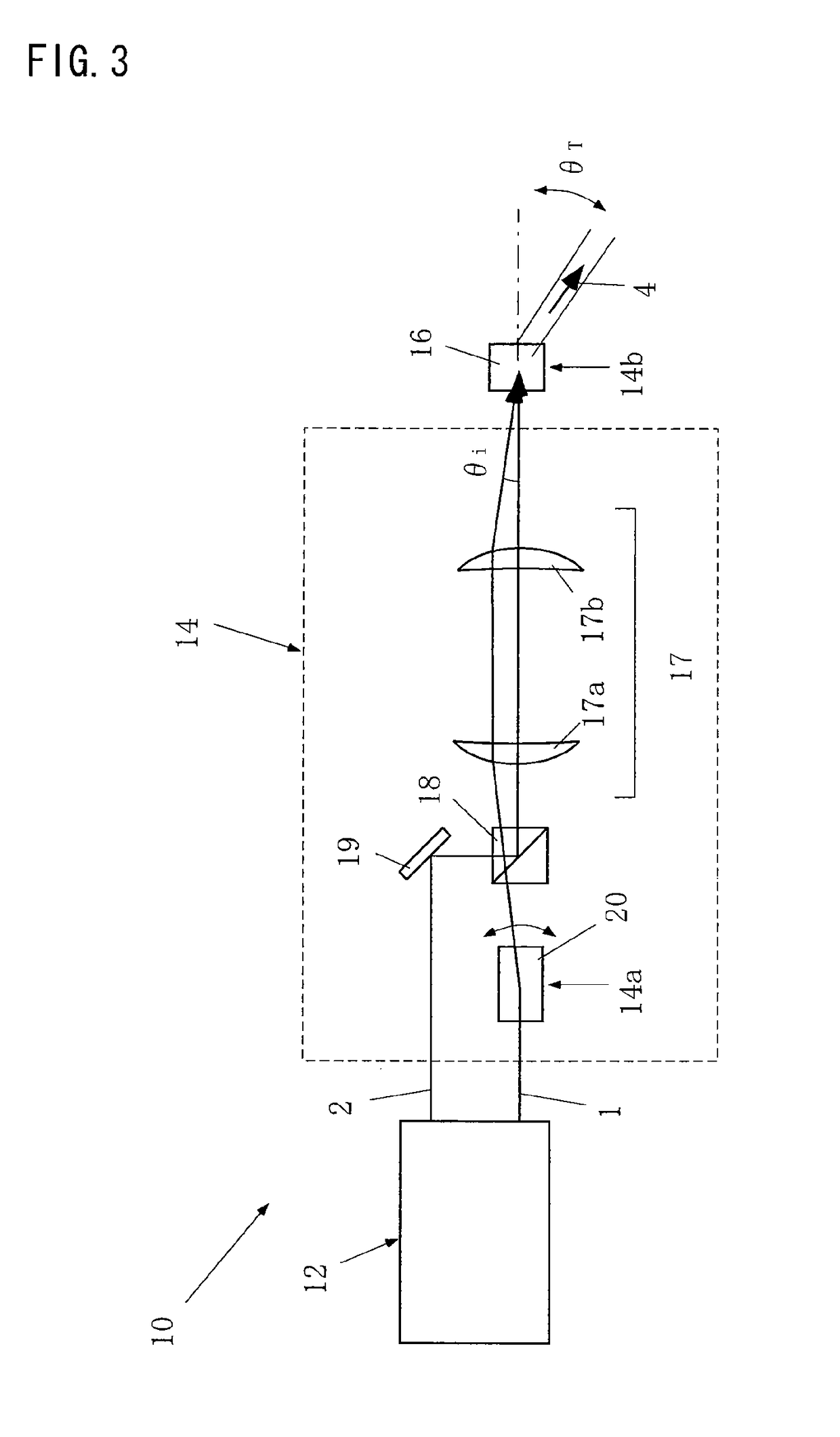
[0088]FIG. 5 is a diagram showing an overall structure of a test apparatus according to the present invention. In the drawing, the laser device 12 is a dual wavelength laser device (OPO) that generates, from the same position, the first laser beam 1 and the second laser beam 2 having different wavelengths, simultaneously in the same direction. The laser device 12 has the first laser beam 1 deflected to the laser beam deflection device 20 and the second laser beam 2 deflected to the beam coupler 18, using reflection mirrors 11a, 11b, and 11c and a diffraction grating 13.

[0089]In this example, the nonlinear optical element 16 is PPLN (one type of nonlinear optical element), and the laser beam deflection device 20 is a manually rotated mirror. In the drawing, reference numeral 17c is a λ / 2 wavelength plate, 17d is an auxiliary lens, 25a and 25b are parabolic mirrors, 26 is a knife edge, 27 is a bolometer, and 28 is an oscilloscope.

[0090]The inventors of the present invention manufactur...

example 2

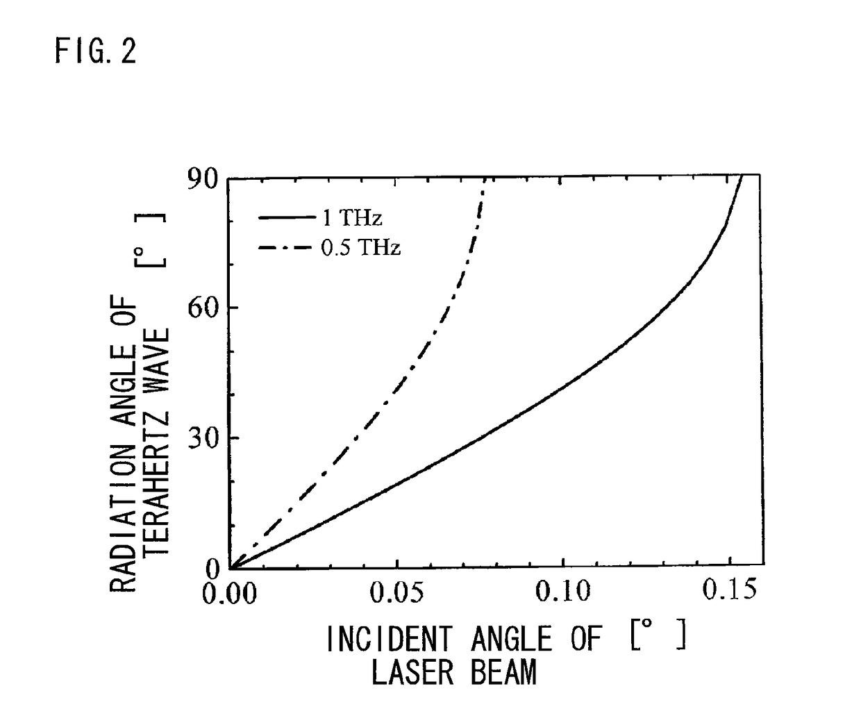
[0109]FIGS. 10 and 11 are diagrams showing test results of the terahertz beam scanning apparatus shown in FIG. 8. FIG. 10 is a diagram showing an intensity distribution of the terahertz beam 4 when changing the incident angle θi of the laser beam 1, and FIG. 11 is a diagram showing a relation of the radiation angle θT of the terahertz beam 4 to the incident angle θi of the laser beam 1.

[0110]From FIG. 10, it can be understood that the traveling direction of the terahertz beam 4 is significantly changed merely by tilting the incident angle θi of the laser beam 1 slightly, as with the result shown in FIG. 6.

[0111]Moreover, from FIG. 11, it can be understood that, when the incident angle θi of the laser beam 1 is changed in a slight range of 0.155°, the terahertz beam 4 is scanned with a magnified angle of 29° which is 187 times 0.155°. In addition, an experimental value is in a good agreement with a calculation value.

[0112]An advantage of the second embodiment lies in that a light uti...

application examples

INDUSTRIAL APPLICATION EXAMPLES

[0129](1) High-speed Nondestructive Inspection Apparatus

[0130]In the case of industrially applying the present invention, due to its high scanning speed, the present invention is effective when measuring a large amount of objects. Terahertz waves have a property of penetrating paper and plastics and reflecting off metals. Hence, it is possible to nondestructively detect, for example, foreign matter such as metal pieces in foods or products. Terahertz waves also have a property of having a unique absorption spectrum depending on substance, so that it is also possible to discover explosives or banned drugs concealed in mail and the like.

[0131]As an example, in a state where an inspection object carried on a carriage such as a belt conveyor is being moved in a product production line or a mail delivery line, the whole inspection object can be imaged to obtain a radioscopic image by scanning a focus of a terahertz wave perpendicularly to the movement of th...


PUM


Abstract

To provide a terahertz beam scanning apparatus and method that can scan a terahertz beam at high speed over a wide angle. The terahertz beam scanning apparatus includes: a laser device 12 that generates a first laser beam 1 and a second laser beam 2 having different wavelengths; a laser optical system 14 that focuses the first laser beam 1 and the second laser beam 2 on a same common focal point 14b; and a terahertz generator 16 that is located at the common focal point and generates a terahertz beam 4 by difference frequency mixing. The laser optical system 14 is configured to be capable of changing a relative incidence θi between the first laser beam and the second laser beam to the terahertz generator.

Description

[0001]This is a National Phase Application in the United States of International Patent Application No. PCT / JP2009 / 057909 filed Apr. 21, 2009, which claims priority on Japanese Patent Application No. 2008-115034, filed Apr. 25, 2008. The entire disclosures of the above patent applications are hereby incorporated by reference.BACKGROUND OF THE INVENTION[0002]1. Technical Field of the Invention[0003]The present invention relates to a terahertz beam scanning apparatus and method for scanning a terahertz beam.[0004]2. Description of the Related Art[0005]Terahertz waves are electromagnetic waves that lie between radio waves and infrared radiation and are 0.3 THz to 10 THz in frequency (30 μm to 1 mm in wavelength). Such terahertz waves have penetrability to various substances such as paper and plastics and a proper spatial resolution, and are expected to serve as a practical tool for radioscopic imaging of various objects. Previous studies have demonstrated usefulness of terahertz waves....

Claims


Application Information

Patent Timeline
Patent Type & Authority Patents(United States)
IPC IPC(8): H01S3/10
CPCH01Q3/42H01Q19/06H01Q19/062G02F2203/13G02F1/3534
Inventor MAKI, KEN-ICHIROSHIBUYA, TAKAYUKIOTANI, CHIKOKAWASE, KODO
Owner RIKEN
Why Eureka
Try Eureka