Method for estimating vehicular running state, vehicular running state estimating device, vehicle control device, and tire wheel

a vehicle running state and vehicle control technology, applied in specific gravity measurement, instruments, roads, etc., can solve the problems of low measurement accuracy, easy to affect road surface friction coefficient, difficult to accurately estimate the running state of the vehicle, etc., and achieve accurate estimation

Inactive Publication Date: 2006-04-25
BRIDGESTONE CORP
View PDF22 Cites 23 Cited by
  • Summary
  • Abstract
  • Description
  • Claims
  • Application Information

AI Technical Summary

Benefits of technology

[0015]To attain the above object, the inventor of the present invention has conducted various studies and has found that the running state of a vehicle such as the condition of a road surface or the running state of each tire while running is estimated by detecting the vibration level of a portion below the spring of a running vehicle or the vibration transmission level between at least two points of a portion below the spring of the vehicle, thereby making it possible to estimate the running state of the vehicle accurately even when the road is rough, which has been difficult with the prior art, or when the slip angle is null. The present invention has been accomplished based on this finding.
[0067]According to a thirty-fourth aspect of the present invention, there is provided a tire wheel comprising the vehicle running state estimation apparatus as set forth in any one of claims 6 to 26 and a electric power generating unit for generating power by the rolling of each tire and supplying power to the above vehicle running state estimation apparatus. Therefore, as the running state of the vehicle can be estimated for a long time without changing the structure of the vehicle body, the running state of the vehicle can be controlled stably.
[0069]According to a thirty-sixth aspect of the present invention, there is provided a tire wheel, wherein the power generating unit comprises a rotor magnetized and rotated by the rolling of each tire, a stator made from a high magnetic permeability material and adjacent to the rotor and a power generating coil installed within a magnetic circuit including the rotor and the stator. Therefore, power supply to the above vehicle running state estimation apparatus is made possible semi-permanently and its functions can be retained for a long time.
[0070]According to a thirty-seventh aspect of the present invention, there is provided a tire wheel, wherein the power generating unit comprises means of accumulating electromotive force generated in the above power generating coil. Therefore, stable power supply is possible regardless of the running state of the vehicle.

Problems solved by technology

However, in the above method of estimating a road surface friction coefficient from the uniformity level of the tire, the uniformity is deteriorated by the formation of a flat spot in the tire and in the course of recovery from this, accurate estimation is difficult.
Meanwhile, in the above method of estimating a road surface friction coefficient from the horizontal-direction vibration of the front wheels having a toe angle, the measurement accuracy is low when the slip angle of the tire is taken completely null or large.
However, as the road surface friction coefficient is estimated from vibration transmission characteristics between two points through a suspension unit having large buffer characteristics such as a spring or damper, the road surface friction coefficient is readily affected by the uneven surface of the road.
For instance, as vibration under a spring is large on a rough road such as a road covered with snow, the difference in vibration level between vibration above the spring absorbed by a suspension and vibration below the spring becomes large, thereby making it impossible to estimate a road surface friction coefficient accurately.
However, the structure of the vehicle body must be changed for means of supplying power to these, thus boosting costs.
Although it can be said that it is the most realistic method to load batteries which are to be exchanged, there remain such problems as the troublesome exchange and service life of the batteries.

Method used


Image

  • Method for estimating vehicular running state, vehicular running state estimating device, vehicle control device, and tire wheel
  • Method for estimating vehicular running state, vehicular running state estimating device, vehicle control device, and tire wheel
  • Method for estimating vehicular running state, vehicular running state estimating device, vehicle control device, and tire wheel

Examples


embodiment 1

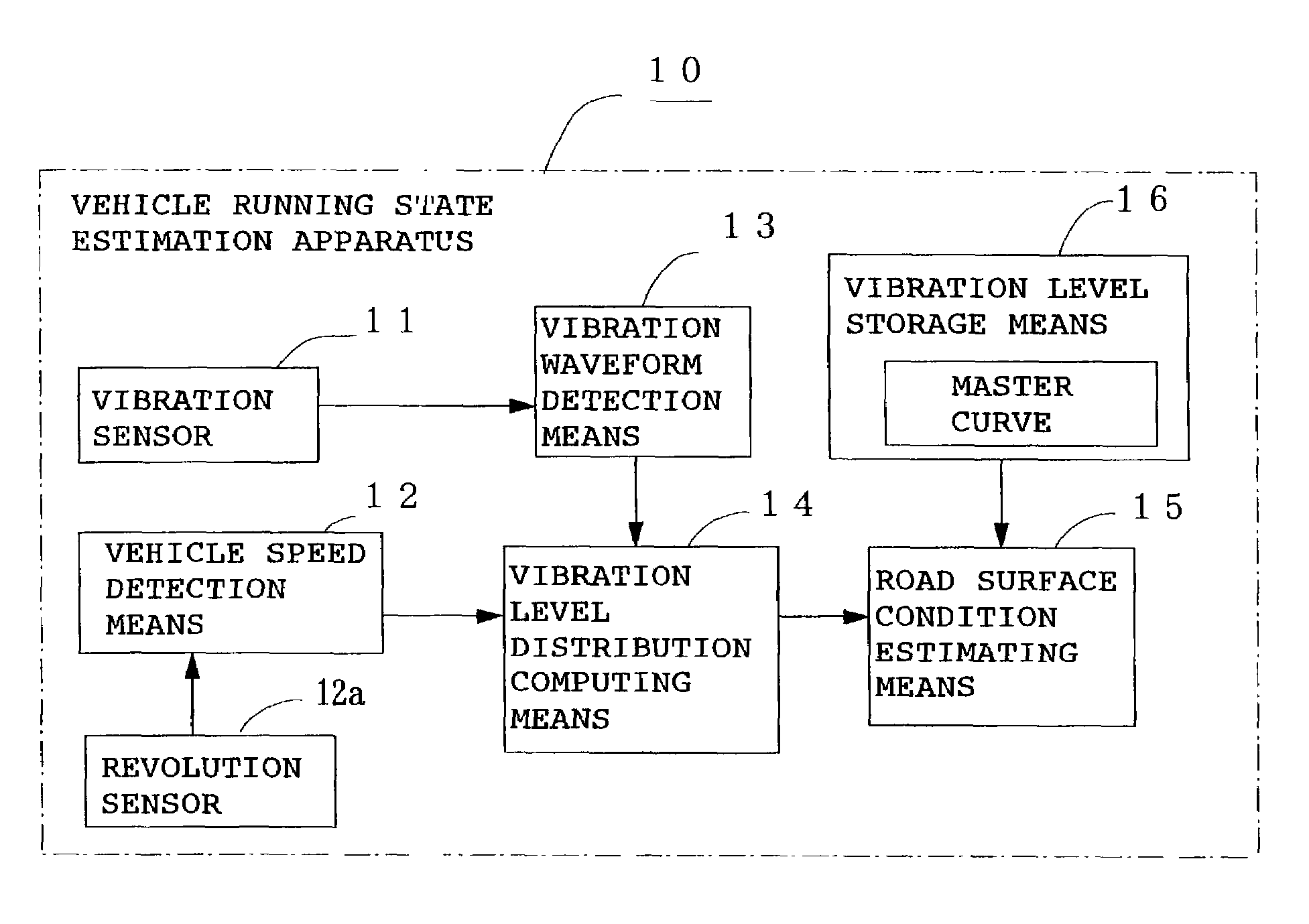
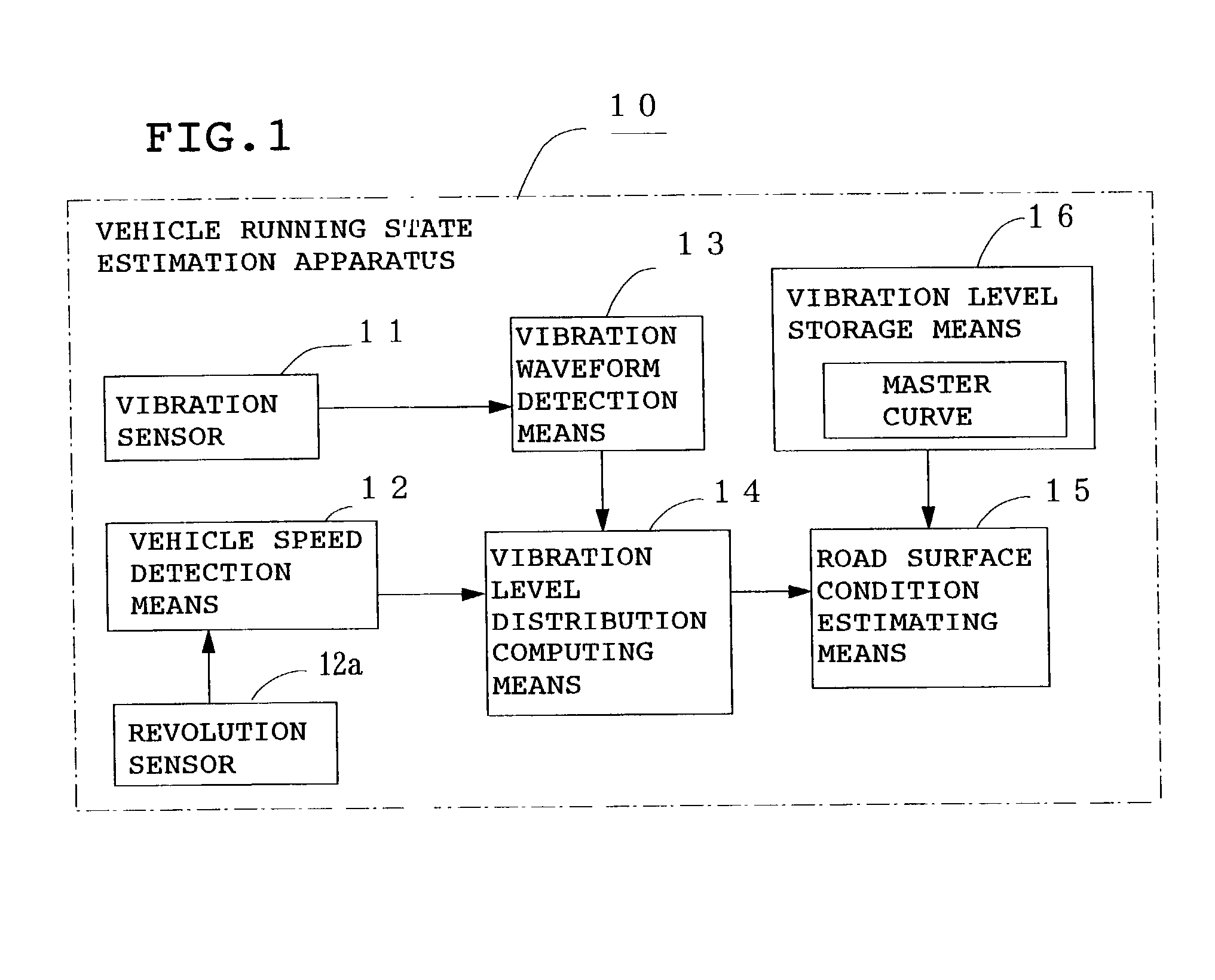
[0098]FIG. 1 is a block diagram showing the constitution of a vehicle running state estimation apparatus 10 according to Embodiment 1 of the present invention. In the figure, reference numeral 11 denotes a vibration sensor installed on the inner surface of a tire tread, 12 vehicle speed detection means for detecting vehicle speed based on the output pulse of a revolution sensor 12a for detecting the speed of a wheel, 13 vibration waveform detection means for obtaining the waveform of vibration by arranging the output levels (vibration levels) of the above vibration sensor in time sequence, 14 vibration level distribution computing means for obtaining the vibration level distribution of a tire tread by computing the vibration levels in a leading edge portion, a ground contact portion and a trailing edge portion of the tire using the output pulses of the above revolution sensor 12a, and 15 road surface condition estimation means for estimating the condition of a road surface which is ...

embodiment 2

[0113]In the above Embodiment 1, the vibration levels of a portion below the spring of the vehicle measured by the vibration sensor 11 are arranged in time sequence by the vibration waveform detection means 13 and the vibration level distribution of the tread 1 is obtained by the vibration level distribution computing means 14 to estimate the condition of a road surface. As shown in FIG. 6, frequency analyzing means 14F for obtaining the frequency spectrum of vibration level obtained by converting the frequency of the above vibration level and vibration level calculating means 14S for calculating a vibration level at a predetermined frequency band of the obtained frequency spectrum are provided in place of the above vibration level distribution computing means 14, and further road surface condition estimation means 15S for estimating the condition of a road surface by comparing the vibration level calculated by the above vibration level calculating means 14S with a master curve for ...

embodiment 3

[0118]In the above Embodiment 2, the condition of a road surface is estimated from the vibration level at a predetermined frequency band calculated by the vibration level calculating means 14S. As shown in FIG. 8, vibration level computing means 14 for computing at least two vibration levels at different frequency bands of the obtained frequency spectrum is provided in place of the above vibration level calculating means 14s, and road surface condition estimation means 15S for estimating the condition of a road surface by comparing the computed value of vibration level computed by the above vibration level computing means 14R with a master curve for estimating the condition of a road surface from the frequency spectrum of vibration level stored in the vibration level storage means 16R is provided to estimate the condition of a road surface.

[0119]The above two frequency bands are preferably 300 to 1,000 Hz which is hardly affected by the condition of a road surface and 800 to 5,000 H...


PUM

PropertyMeasurementUnit
frequencyaaaaaaaaaa
frequencyaaaaaaaaaa
friction coefficientaaaaaaaaaa

Abstract

The output level of vibration of a portion below the spring of a vehicle detected by a sensor, and its frequency is converted to obtain the frequency spectrum of the vibration level. Next, an operation is carried out on at least two vibration levels, at different frequency bands. The computed value is compared with a master curve showing the frequency spectrum of vibration level stored in vibration level storage to estimate the condition of a road surface so as to estimate the running state of the vehicle. Further, the running state of each tire including air pressure is detected from the vibration level of the portion below the spring to estimate the running state of the vehicle. Thereby, a multi-function sensing system is constructed for estimating the condition of a road surface or the running state of the tire with one sensor.

Description

BACKGROUND OF THE INVENTION[0001]1. Field of the Invention[0002]The present invention relates to a method and apparatus for estimating the running state of a vehicle by estimating the condition of a road surface or the running state of each tire while running, an apparatus for controlling a vehicle based on the estimated running state of a vehicle, and a tire wheel comprising the above vehicle running state estimation apparatus and a power generating unit for activating this apparatus.[0003]2. Description of the Prior Art[0004]In recent years, it has been desired that the relationship between each tire and the surface of a road which is the most important factor for the safe running of a vehicle, specifically, the ground contact state of the tire typified by a friction coefficient between the tire and the surface of a road (road surface friction coefficient) or the condition of a road surface, or the running state of the tire such as the distortion and air pressure of the tire shoul...

Claims


Application Information

Patent Timeline
Patent Type & Authority Patents(United States)
IPC IPC(8): G01B5/28B60C23/06B60G17/0165B60G17/019B60G17/0195B60T8/172G01H1/00G01H1/12G01H1/14G01N3/06G01N9/24G01N19/02
CPCB60C23/06B60C23/065B60G17/019B60G17/0195B60T8/172G01H1/003G01H1/12G01H1/14G01N19/02B60G17/0165B60G2204/11B60G2204/113B60G2400/102B60G2400/204B60G2400/206B60G2400/208B60G2400/52B60G2400/821B60G2400/91B60G2600/02B60G2600/188B60G2600/60B60G2600/604B60G2800/162B60G2800/70B60G2800/702B60G2800/916B60T2210/12B60T2210/13G01N9/24G01N2203/0676G01N2203/0682G01N2203/0688
Inventor YOKOTA, HIDETOSHIMORINAGA, HIROSHIOTANI, KOJI
Owner BRIDGESTONE CORP
Why Eureka
Try Eureka