Cooling device for a wind turbine generator

a cooling device and wind turbine technology, applied in the direction of wind energy generation, machines/engines, magnetic circuit shapes/forms/construction, etc., can solve the problems of acoustic disturbance and interference of mechanical vibrations and oscillations of the generator, which are perceived as acoustic disturbance and interference, and involve regular losses

Inactive Publication Date: 2006-04-25
WOBBEN ALOYS
View PDF13 Cites 32 Cited by
  • Summary
  • Abstract
  • Description
  • Claims
  • Application Information

AI Technical Summary

Benefits of technology

[0016]FIG. 1 shows a simplified side view of a wind power installation according to the invention, and
[0017]FIG. 2 shows a simplified detail view of an alternative embodiment of the present invention.

Problems solved by technology

The conversion of energy regularly involves losses in the form of heat.
That naturally also applies in regard to the conversion of the kinetic energy of the wind into electrical energy in the generator of a wind power installation, those losses also regularly occurring in the main drive train of the wind power installation.
In the main drive train which is disposed in the pod of the wind power installation, the losses occur for the major part in the generator.
That known structure however suffers from the disadvantage that mechanical vibrations and oscillations of the generator can be perceived as acoustic disturbance and interference.

Method used


Image

  • Cooling device for a wind turbine generator
  • Cooling device for a wind turbine generator
  • Cooling device for a wind turbine generator

Examples


Embodiment Construction

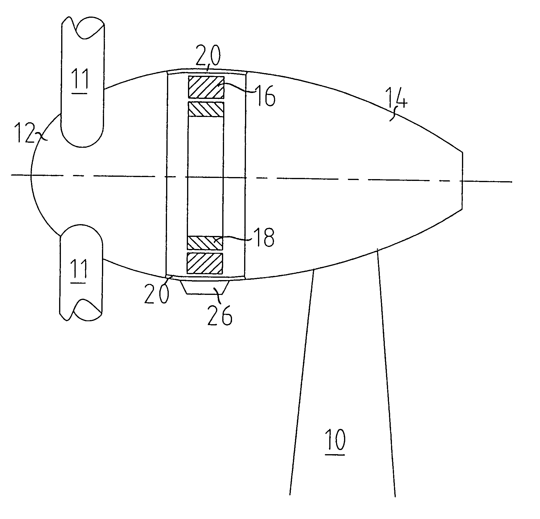
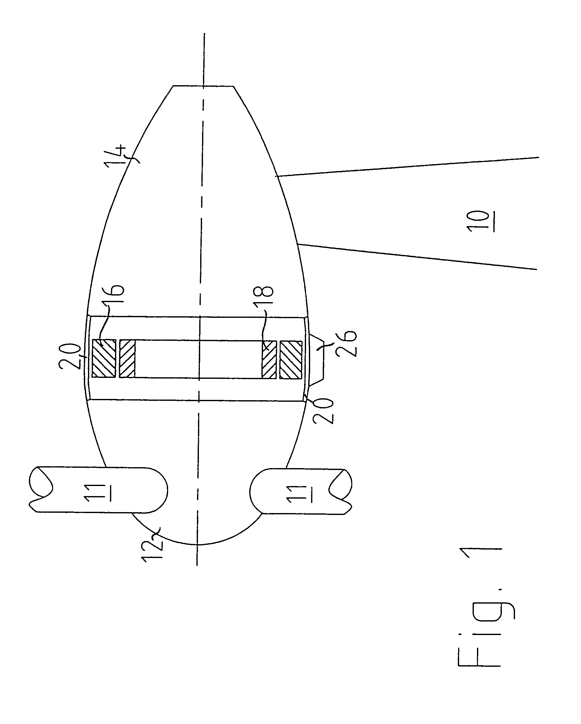
[0018]In FIG. 1 reference 10 denotes the upper portion of a pylon which carries the pod of the wind power installation according to the invention. That pod has a front portion 12 and a rear portion 14.

[0019]The front portion 12 includes the roots of the rotor blades 11 of which portions are shown, and it rotates with the rotor.

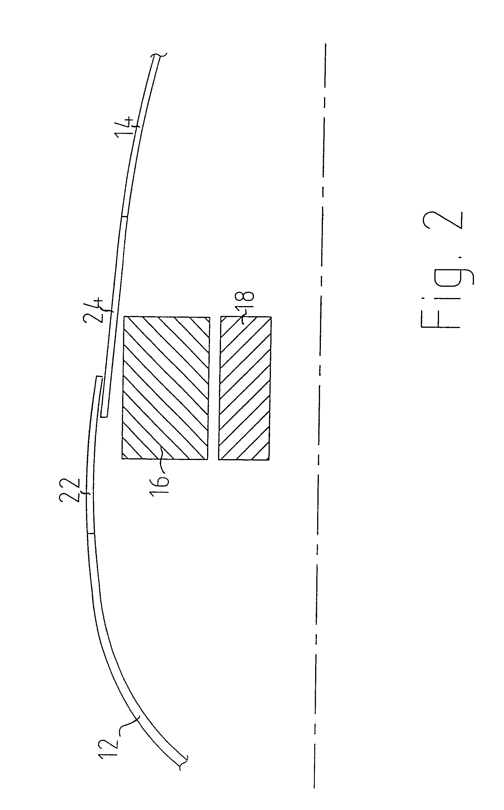
[0020]The rear portion 14 encloses the ring generator with its stator 16 and its rotor 18. Accordingly, the stator 16, like the rear region of the pod 14, is stationary while the rotor 18 co-operates by means of the wind power installation rotor hub (not shown) with the rotor blades 11.

[0021]In the region of the generator 16, 18 at a predetermined spacing relative thereto a portion 20 of the rear part of the pod housing 14 is formed from a heat-conducting material, preferably aluminum. That heat-conducting housing portion 20 receives the heat emitted by the generator 16, 18 and discharges it to the ambient air flowing therepast. By virtue of the predetermined ...


PUM


Abstract

The present invention concerns a wind power installation comprising a ring generator and a housing having a heat-conducting housing portion in the region of the ring generator. Previously known structures suffer from the disadvantage that mechanical vibrations and oscillations of the generator can be perceived as acoustic disturbance and interference. The object of the present invention is very substantially to eliminate that disadvantage. A wind power installation comprising a ring generator and a pod housing, which surrounds the ring generator, of the wind power installation, wherein the pod housing has a heat-conducting housing portion in the region of the ring generator and a predetermined spacing is provided between the outside periphery of the ring generator and the heat-dissipating housing portion.

Description

BACKGROUND OF THE INVENTION[0001]1. Field of the Invention[0002]The present invention concerns a wind power installation comprising a ring generator and a housing having a heat-conducting housing portion in the region of the ring generator.[0003]2. Description of the Related Art[0004]The conversion of energy regularly involves losses in the form of heat. That naturally also applies in regard to the conversion of the kinetic energy of the wind into electrical energy in the generator of a wind power installation, those losses also regularly occurring in the main drive train of the wind power installation. In the main drive train which is disposed in the pod of the wind power installation, the losses occur for the major part in the generator.[0005]Hitherto that heat due to energy losses has been discharged to the ambient atmosphere by using fans, either by cold air being sucked in from the exterior or by the heated air being circulated within the pylon and the heat being discharged to ...

Claims


Application Information

Patent Timeline
Patent Type & Authority Patents(United States)
IPC IPC(8): F03D11/00F03D9/00F03D11/04H02K1/18H02K5/04H02K5/18H02K5/24H02K7/18H02K9/22
CPCF03D9/002F03D11/00H02K7/1838H02K9/22F05B2220/7066F05B2260/20F05B2260/2241H02K5/18Y02E10/722Y02E10/725H02K1/185F03D9/25F03D80/60Y02E10/72H02K9/223H02K5/02
Inventor WOBBEN, ALOYS
Owner WOBBEN ALOYS
Why Eureka
Try Eureka