Drive unit equipped with electrical motor

a technology of drive unit and electric motor, which is applied in the direction of electric propulsion mounting, gear mounting, transportation and packaging, etc., can solve the problems of gear noise, unavoidable reduction of the rigidity strength of the supporting wall, and easy oscillation of the counter drive gear, so as to prevent gear noise occurrence, prevent gear misalignment due to oscillation, and prevent the effect of gear nois

Inactive Publication Date: 2006-04-25
AISIN AW CO LTD
View PDF17 Cites 13 Cited by
  • Summary
  • Abstract
  • Description
  • Claims
  • Application Information

AI Technical Summary

Benefits of technology

[0011]In this structure, the counter output shaft is supported at both end portions thereof by the drive unit case, and thus an inclination of the counter output shaft due to a torque-transmission load is inhibited. Accordingly, an oscillated rotation of the counter output shaft is prevented, thereby gear misalignment due to the oscillated rotation is prevente

Problems solved by technology

This causes a problem.
Furthermore, if the introduction portion is provided with space for a cable connection, it is unavoidable that the portion corresponds to an outside circumferential side of the planetary gear set (planetary gear 6) which has a small outer diameter.
Accordingly, rigidity strength of the supporting wall is unavoidably decreased due to the formation of this window hole.
In such circumstances, in the aforeme

Method used


Image

  • Drive unit equipped with electrical motor
  • Drive unit equipped with electrical motor
  • Drive unit equipped with electrical motor

Examples


Embodiment Construction

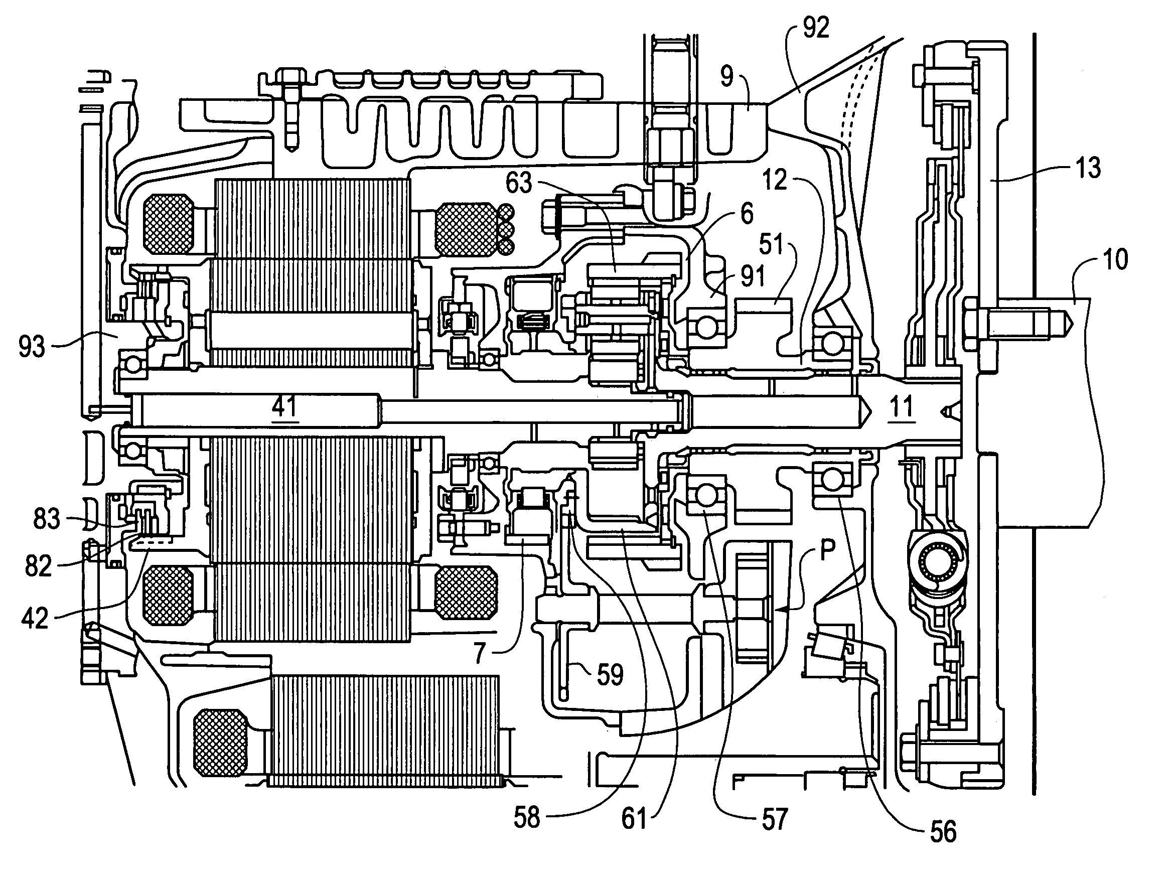
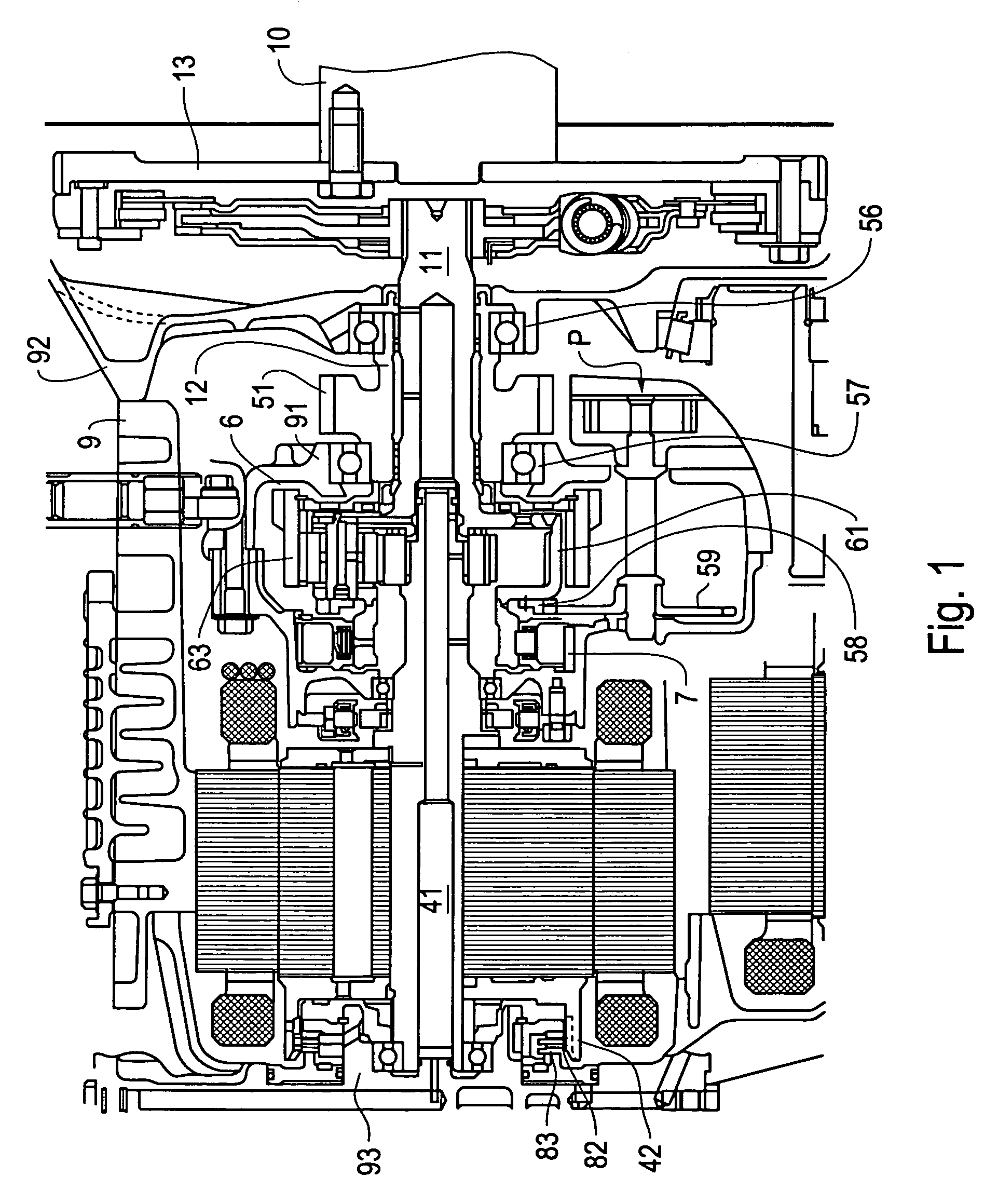
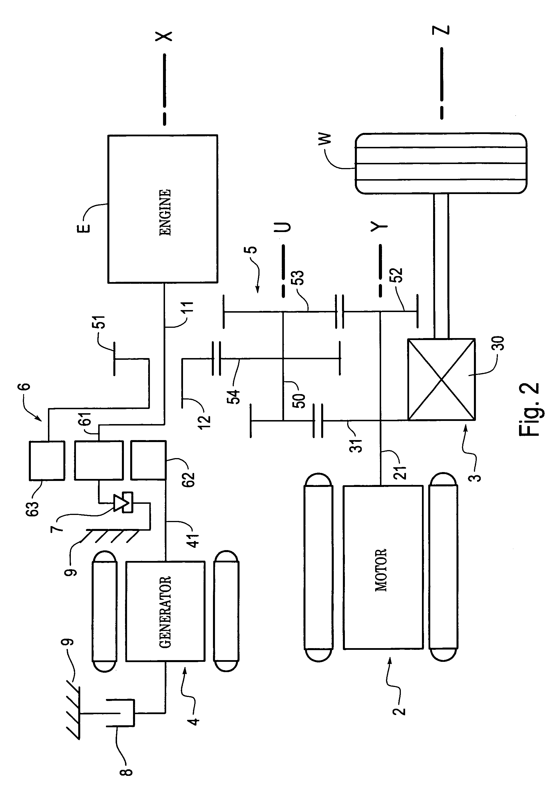
[0017]An embodiment of the invention will be described with reference to the figures. First, FIG. 2 is a skeleton view schematically showing a hybrid drive unit in which the invention is adopted. In this figure, a gear train is developed on a same plane. This unit is provided as a drive unit of a transversely placement type, in which an engine E, an electric motor (motor) 2, and a differential unit 3 are arranged parallel on different axial lines respectively. Hereinafter, these axial lines are referred to as an engine axial line X, an electric motor axial line Y, and a differential axial line Z, in the description of the embodiment. Furthermore, a generator 4 is disposed on the engine axial line X, and a gear train 5 is disposed for drive-connecting the engine E, the motor 2, and the generator 4 to the differential unit 3 on parallel axes. A counter shaft 50 of the gear train 5 is arranged on another axial line (similarly, referred to as a counter axial line U) different from the r...


PUM


Abstract

A drive unit equipped with an electric motor including an input shaft that is connected to an engine, an electric motor shaft, a counter output shaft, and a planetary gear set, wherein the input shaft and the counter output shaft are connected respectively, on one side of the planetary gear set, to two other elements which are different from an element with which the electric motor shaft is connected, an outer circumference of both edge portions of the counter output shaft is supported by a drive unit case, and an outer circumference of the input shaft is supported by an inner circumference of the counter output shaft by the drive unit case through the counter output shaft.

Description

BACKGROUND OF THE INVENTION[0001]1. Field of the Invention[0002]The invention relates to a drive unit for a vehicle equipped with an electric motor.[0003]2. Description of Related Art[0004]A drive unit for an electric vehicle or a hybrid drive unit has been adopted as a drive unit for a vehicle, in which an electric motor is used as a drive source. A similar drive unit has been disclosed in Japanese Patent Laid-Open No. 2001-187535, in which an engine, a generator, and a gear train, which is drive-connected to a wheel through a differential unit, are connected through a planetary gear set. Power can thus mutually transmit among the engine, the generator, and the wheel. Accordingly, the drive unit can freely execute driving of the generator by the engine, assist in the driving force and start the engine when the generator serves as the electric motor, and perform regeneration using an inertia power which is returned from the wheel to the planetary gear set through the differential un...

Claims


Application Information

Patent Timeline
IPC IPC(8): B60K17/04B60K1/02B60K6/20B60K6/24B60K6/26B60K6/365B60K6/405B60K6/445F16H1/28F16H3/72F16H37/06H02K51/00
CPCB60K6/26B60K6/445H02K51/00B60K6/36B60K1/02Y02T10/6239Y02T10/62
Inventor TAKENAKA, MASAYUKI
Owner AISIN AW CO LTD
Why Eureka
Try Eureka