RF power amplifier employing bias circuit topologies for minimization of RF amplifier memory effects
- Summary
- Abstract
- Description
- Claims
- Application Information
AI Technical Summary
Benefits of technology
Problems solved by technology
Method used
Image
Examples
Embodiment Construction
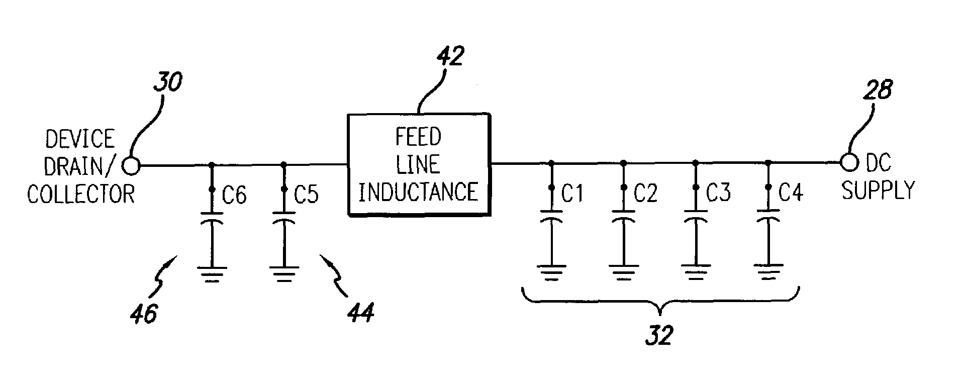
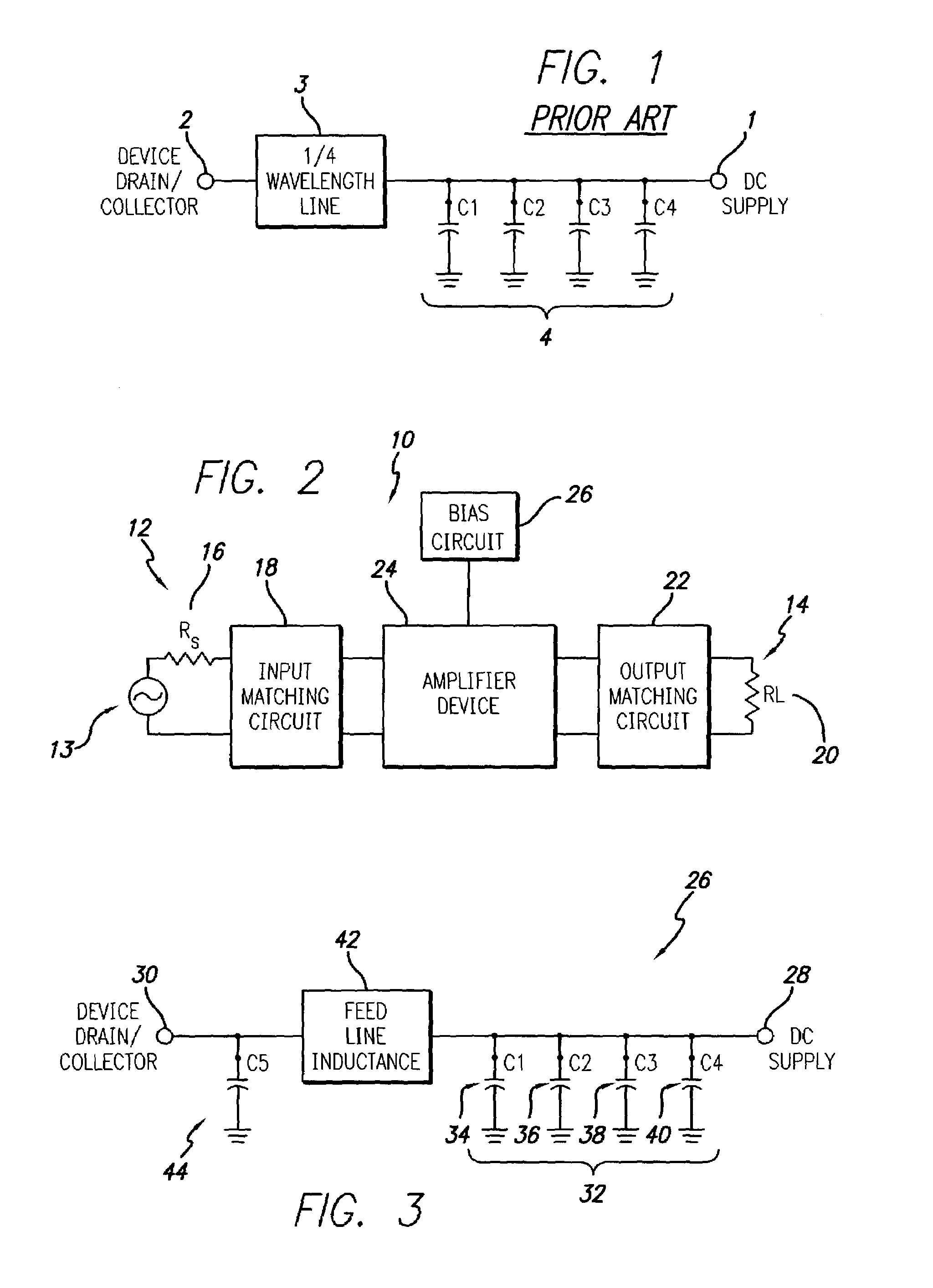
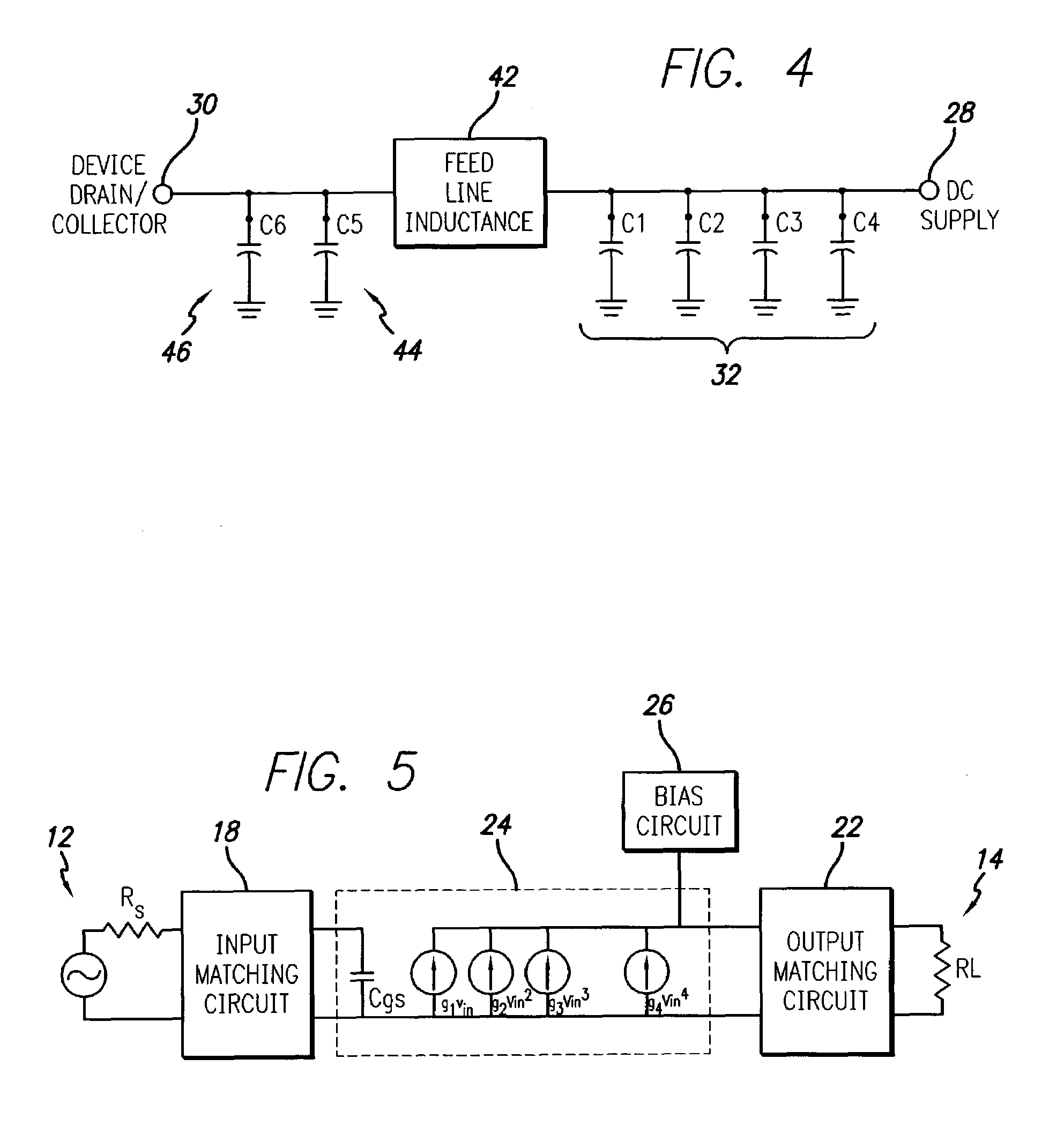
[0034]Referring to FIGS. 2 and 3 a first embodiment of the present invention is illustrated. More particularly, FIG. 2 illustrates an RF power amplifier in block schematic form and FIG. 3 illustrates a schematic drawing of a bias circuit employed in the amplifier of FIG. 2, in accordance with the present invention.
[0035]Referring first to FIG. 2, the amplifier 10 is illustrated in a block schematic drawing. The amplifier 10 includes an input 12 which receives an input RF signal 13 to be amplified and an output 14 at which is output the amplified RF signal. The RF signal may be a wide bandwidth signal such as a CDMA (Code Division Multiple Access) spread spectrum communication signal or W-CDMA (Wideband-Code Division Multiple Access) signal such as in UMTS applications, or other high video bandwidth signal. The video bandwidth may thus be greater than 10 MHz, e.g., 20 MHz for 4-carrier UMTS. The input will have an associated impedance illustrated schematically by the source resistanc...
PUM
 Abstract
Description
Claims
Application Information
 - R&D
- Intellectual Property
- Life Sciences
- Materials
- Tech Scout
- Unparalleled Data Quality
- Higher Quality Content
- 60% Fewer Hallucinations
Browse by: Latest US Patents, China's latest patents, Technical Efficacy Thesaurus, Application Domain, Technology Topic, Popular Technical Reports.
© 2025 PatSnap. All rights reserved.Legal|Privacy policy|Modern Slavery Act Transparency Statement|Sitemap|About US| Contact US: help@patsnap.com


