Optical fiber ring communication system

Inactive Publication Date: 2006-04-25
CIENA
View PDF17 Cites 93 Cited by
  • Summary
  • Abstract
  • Description
  • Claims
  • Application Information

AI Technical Summary

Benefits of technology

[0008]At each node of the network there is a link multiplexer that includes one or more link cards for coupling the link multiplexer to client devices, and one or more multiplexer units for coupling the link multiplexer to the optical links. Each link card includes frame buffers capable of storing numerous Fibre Channel frames that are being transmitted to and from the client device(s) coupled to that link card.

Problems solved by technology

To date, however, the equipment available for providing data communications over these networks has

Method used


Image

  • Optical fiber ring communication system
  • Optical fiber ring communication system
  • Optical fiber ring communication system

Examples


Embodiment Construction

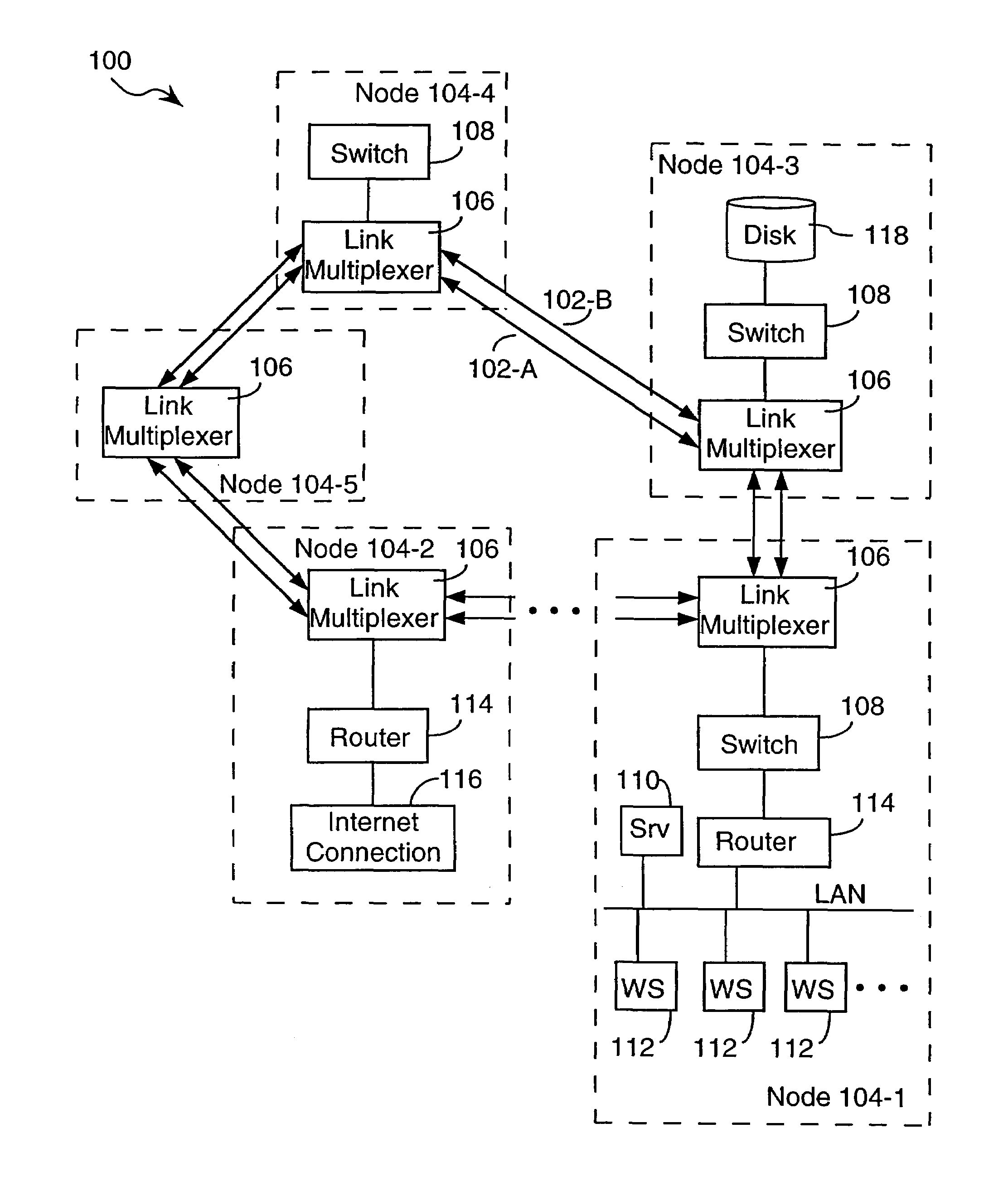
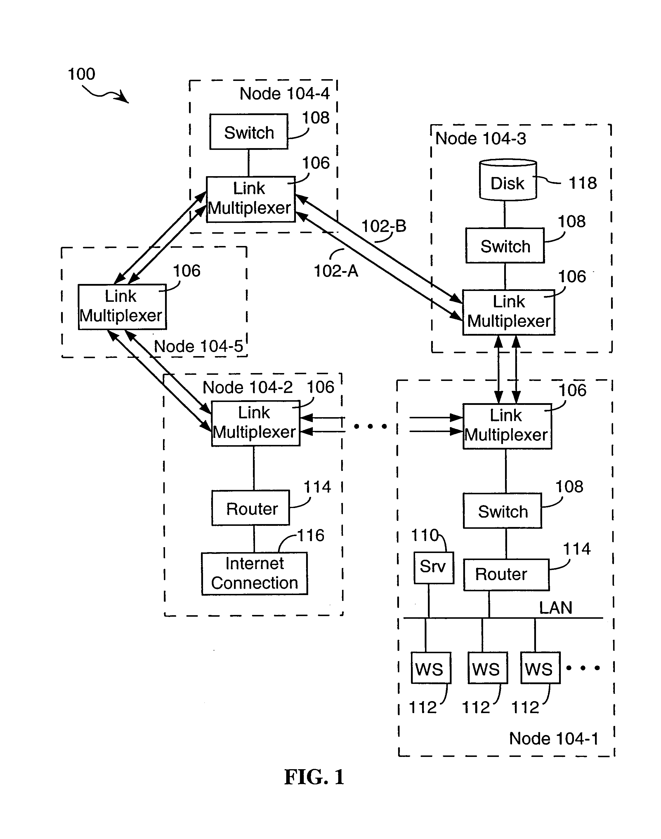
[0026]Referring to FIG. 1, there is shown a fiber optic ring network 100. The network includes a pair of fiber optic cables 102 that traverse a loop or ring. At each node 104 of the network, the fiber optic cables are segmented so that signals on the pair of fiber optic cables are received by the link multiplexer 106 at that node, and then either processed or forwarded to the next segment of the fiber 102.

[0027]The link multiplexers 106 perform numerous functions: forwarding signals from one optical fiber segment to the next, routing signals from the optical fiber cables to client devices or communication lines, and routing signals to the optical fiber cables from client devices or communication lines. The link multiplexers 106 also combine signals from multiple sources using time division and wavelength division techniques so as to transmit them over the fiber optic cables 102.

[0028]The link multiplexer 106 at each node 104 is typically coupled to other devices or communication lin...


PUM


Abstract

An optical fiber ring network includes a plurality of interconnected nodes, each pair of neighboring nodes being interconnected by a pair of optical links. Using coarse wavelength division multiplexing, data is transmitted in both directions over each link, using a first wavelength λ1 to transmit data in a first direction over the link and a second wavelength λ2 to transmit data in a second, opposite direction over the link. The two wavelengths λ1 and λ2 differ by at least 10 nm. Each of the data streams transmitted over the optical link has a bandwidth of at least 2.5 Gbps. Further, each data stream has at least two logical streams embedded therein. A link multiplexer at each node of the network includes one or more link cards for coupling the link multiplexer to client devices, and one or more multiplexer units for coupling the link multiplexer to the optical links. Each link card includes frame buffers capable of storing numerous Fiber Channel frames that are being transmitted to and from the client device(s) coupled to that link card. The link card also includes flow control logic for pre-filling the frame buffers with frames of data before the receiving client devices send flow control messages to request their transmission. The combined effect of the frame buffers and flow control logic is that the full bandwidth of the links can be utilized even when the network nodes are very far apart and the client devices have small input data buffers.

Description

[0001]This application is a Divisional of application Ser. No. 09 / 660,388, filed on Sep. 12, 2000, now U.S. Pat. No. 6,718,139, the entire contents of which are hereby incorporated by reference and for which priority is claimed under 35 U.S.C. § 120.[0002]This appln claims the benefit of 60 / 153,519 filed on Sep. 13, 1999.[0003]The present invention relates generally to optical fiber communication systems, and particularly to a system architecture for making efficient use of optical fiber communication rings and provided reliable logical connections between network nodes.BACKGROUND OF THE INVENTION[0004]Fiber optic rings have been installed, and as of 1999 are in the process of being installed in many cities. These communication networks have the potential to provide low cost, high bandwidth connections within a geographical area of several miles, as well as low cost, high bandwidth connections to other communication networks, such as the Internet. To date, however, the equipment ava...

Claims


Application Information

Patent Timeline
IPC IPC(8): H04B10/20H04J14/02H04Q11/00
CPCH04J14/0227H04J14/0283H04J14/0241H04Q11/0067H04Q11/0005H04J14/0226H04J14/0287H04Q11/0071H04Q2011/0075H04Q2011/0092
Inventor FINAN, CHRISTOPHER D.FARLEY, MARK
Owner CIENA
Why Eureka
Try Eureka