Composite valve

a composite valve and valve body technology, applied in the field of composite valves, can solve the problems of affecting the operation of valves, and affecting the operation of valves, and achieve the effects of reducing cost, reducing parts cost and power consumption, and simplifying the construction of composite valves

Inactive Publication Date: 2006-05-02
FUJIKOKI CORP
View PDF5 Cites 7 Cited by
  • Summary
  • Abstract
  • Description
  • Claims
  • Application Information

AI Technical Summary

Benefits of technology

[0006]Accordingly, the object of the present invention relates to provide a composite valve, having a simple small valve configuration and capable of being manufactured with reduced man-hour and at restricted cost.
[0014]According to the present invention arranged in this manner, two solenoid valves that are conventionally required may be replaced with a single composite valve. Thus, the parts cost and power consumption can be lowered, and the number of essential parts can be cut to ensure a reduction in cost. In consequence, the valve configuration cannot be large-sized, the construction of the composite valve can be simplified, and the entire system can be reduced in weight.
[0015]Further, the manufacturing man-hour can be reduced to lower the machining cost. Since components that constitute the differential pressure valve are not exposed to the outside, moreover, there is no possibility of a refrigerant leaking out. Furthermore, the general configuration of the refrigerating cycle to which the composite valve is applied can be simplified.
[0016]Besides, the main valve element pressure equalizing hole serves to equalize the pressures in the upper valve chest and the pilot valve chest, thereby facilitating and smoothing the open-close action of the main valve element. Furthermore, the pressure equalizing hole allows the refrigerant in the upper valve chest to flow out quickly into the pilot valve chest, thereby making it impossible or hard for the main valve to open, if a compressor is actuated, for example, with the main valve closed so that the pressure on the main valve is suddenly changed by the compressor.
[0017]If the valve is provided with the restraining means, excessive deflection of the diaphragm can be restrained to prevent sagging or deformation of the diaphragm. Further, the durability of the diaphragm that constitutes the differential pressure valve portion can be improved. Since the restraining means is formed integrally with the valve body, moreover, the configuration and manufacture of the valve can be simplified.

Problems solved by technology

The conventional composite valve, however, is bulky and complicated in configuration, since it combines a solenoid on-off valve and a differential pressure valve.
Thus, its manufacturing man-hour and machining cost tend to increase.
According to the one described in Japanese Patent Application Laid-Open No. 2001-124440, moreover, elements that constitute the differential pressure valve are exposed to the outside, so that refrigerant leakages may be caused in some cases.

Method used


Image

  • Composite valve
  • Composite valve
  • Composite valve

Examples


first embodiment

[0038][First Embodiment]

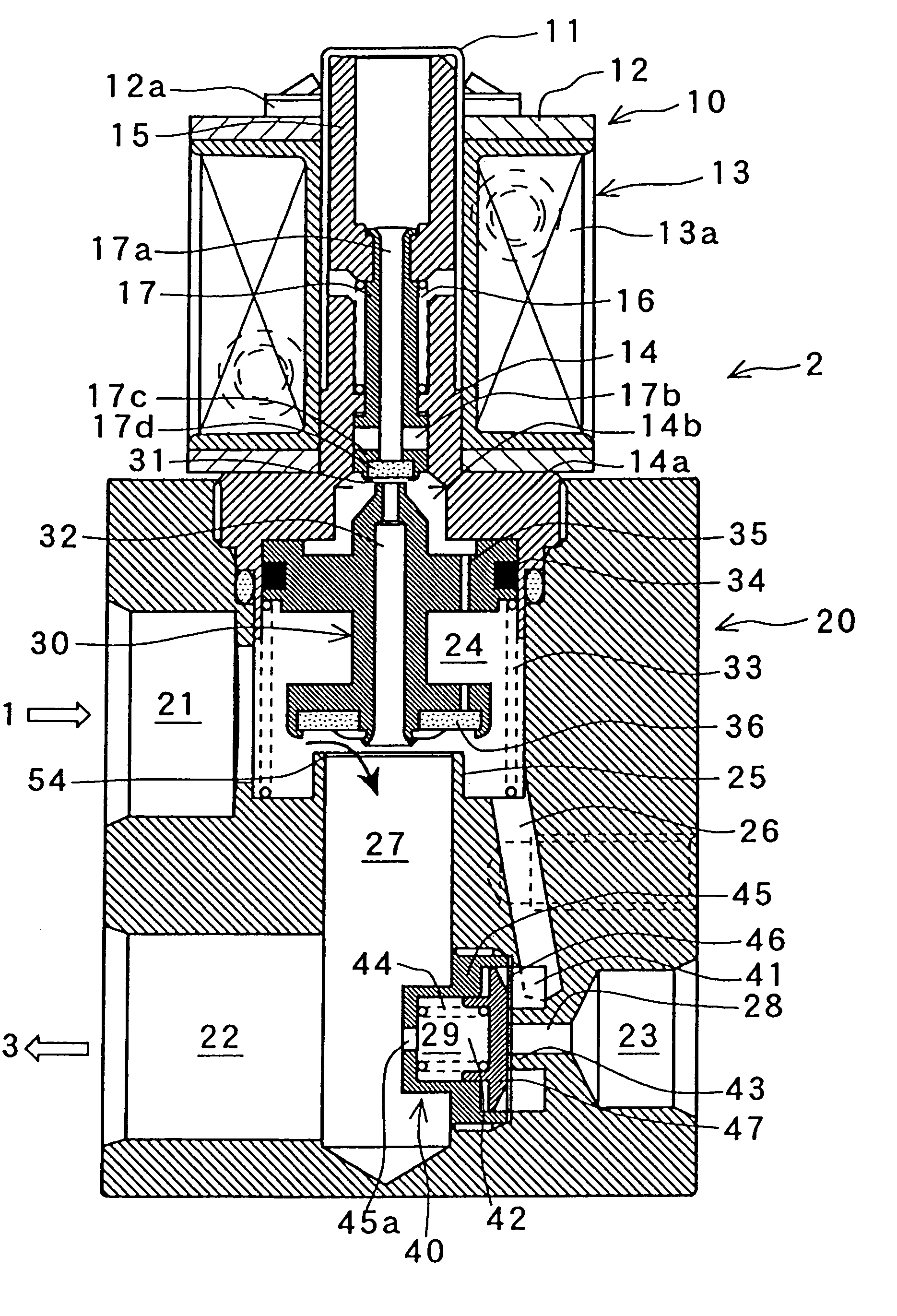
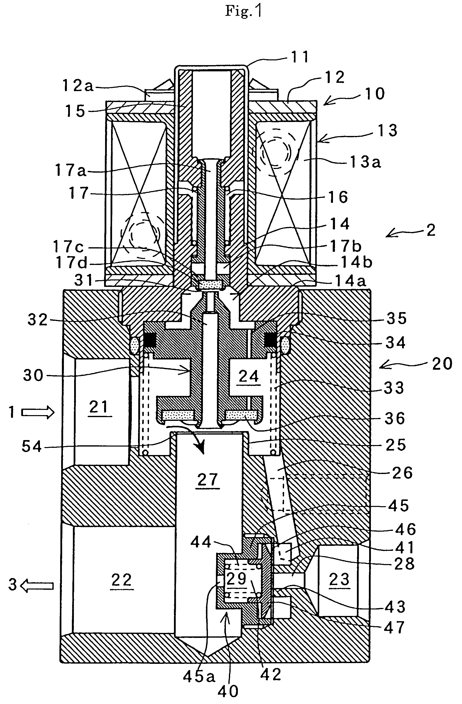
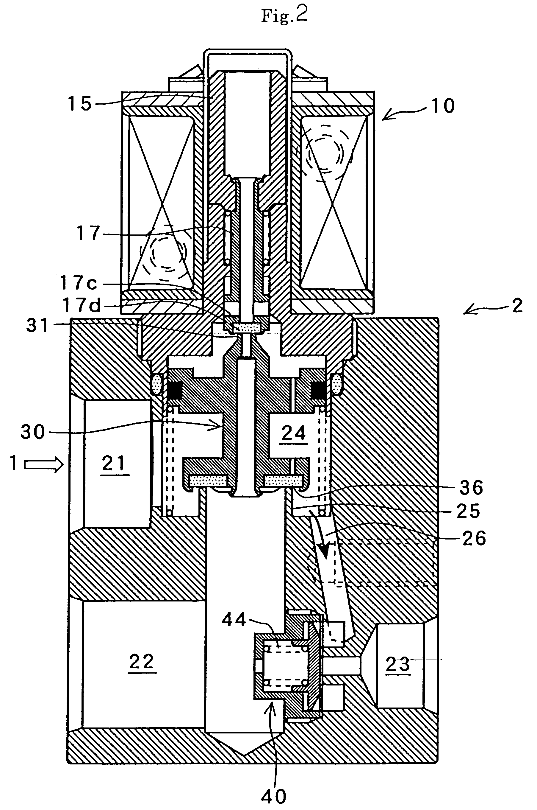
[0039]A first embodiment will first be described with reference to FIGS. 1 to 4 and FIG. 10.

[0040]A composite valve 2 of the invention is applied to a refrigerating cycle that is provided with a hot-gas defrosting cycle, such as the one shown in FIG. 10. This refrigerating cycle is a conventional one, in which a compressor 1, the composite valve 2, a condenser 3, a liquid receiver 4, a check valve 5, an evaporator 6, and an accumulator 7 are coupled to one another by means of piping 8. FIGS. 1 to 3 show the composite valve used in this cycle. Further, the composite valve 2 and the piping 8 at the inlet of the evaporator 6 are coupled like a bypass by means of a bypass pipe 9.

[0041]As shown in FIG. 1, the composite valve 2 comprises a valve body 20, a solenoid valve portion 10, and a differential pressure valve portion 40. The valve portions 10 and 40 are attached to the body 20. In the solenoid valve portion 10, open-close control of a refrigerating cycle tha...

second embodiment

[0071][Second Embodiment]

[0072]A second embodiment of the invention will now be described with reference to FIGS. 5 to 9 and FIG. 11. In the description of the second embodiment to follow, the same components of the second embodiment as those of the first embodiment are denoted the same reference numerals in FIGS. 5 to 9 and FIG. 11 as those used in FIGS. 1 to 4 and FIG. 10, and description of those components is omitted here.

[0073]A composite valve 2′ according to the second embodiment, which is based on the general configuration of the first embodiment, is characterized in that a check valve portion 50 is attached to a valve body 20. Its solenoid valve portion 10 and differential pressure valve portion 40 are constructed in the same manner as the ones according to the first embodiment. The valve portions 10 and 40 act without regard to the attachment of the check valve portion 50.

[0074]As shown in FIG. 5, the check valve portion 50 is formed adjacent to the solenoid valve portion ...

third embodiment

[0083][Third Embodiment]

[0084]A third embodiment of the invention will now be described with reference to FIGS. 12 to 16.

[0085]In the description of the third embodiment to follow, the same components of the third embodiment as those of the first embodiment are denoted the same reference numerals in FIGS. 12 to 16 as those used in FIGS. 1 to 4 and FIG. 10, and description of those components is omitted here.

[0086]In the composite valve 2 of the first embodiment, the diaphragm 46 sometimes may bend (to form a flexure 46′a) and be deformed on the side of the communication hole 28 by a force of differential pressure from the closed differential pressure valve element 47, as shown in FIG. 16.

[0087]According to the third embodiment, deformation of a diaphragm 46′ is prevented in a manner such that a stopper 70 is located in a communication hole 28′ to restrain deflection of a deformed diaphragm 46′.

[0088]In the third embodiment, as shown in FIG. 12 or 13, a solenoid valve portion 10, val...


PUM


Abstract

Disclosed is a composite valve comprising a valve body that is provided integrally with a solenoid valve portion and a differential pressure valve portion. The valve body is formed with an upper valve chest, a lower valve chest, a refrigerant introduction chamber that communicates with the upper valve chest and has a differential pressure valve seat, and a back pressure introduction chamber that communicates with the lower valve chest. A main valve element that is opened and closed by means of the solenoid valve portion is located between the upper valve chest and the lower valve chest. A differential pressure valve element that is opened and closed by means of a differential pressure between the refrigerant introduction chamber and the back pressure introduction chamber is located between these two chambers. The refrigerant introduction chamber, back pressure introduction chamber, and differential pressure valve element are arranged so as not be situated on the outer surface of the valve body.

Description

BACKGROUND OF THE INVENTION[0001]1. Field of the Invention[0002]The present invention relates to a composite valve used in an air conditioning system with a hot-gas defrosting cycle or the like, and more particularly, to a composite valve formed of a solenoid valve portion and a differential pressure valve portion, and to a composite valve formed of a solenoid valve portion, differential pressure valve portion, and check valve.[0003]2. Description of the Related Art[0004]There is proposed an air conditioning system that uses a high-temperature, high-pressure gaseous refrigerant (hot gas) in a refrigerating cycle, thereby enjoying improved heating start-up ability in the initial stage of air conditioning. A composite valve described in Japanese Patent Application Laid-Open No. 2001-124440 or 2002-115937 may be used in the refrigerating cycle for this air conditioning system.[0005]The conventional composite valve, however, is bulky and complicated in configuration, since it combines a...

Claims


Application Information

Patent Timeline
Patent Type & Authority Patents(United States)
IPC IPC(8): F16K11/18F16K27/02F16K31/40F16K31/42F25B41/04F25B41/06F25B47/02
CPCF16K31/423F25B41/04F25B41/06F25B2600/2519F25B2400/0403F25B2600/2505F25B47/022F16K31/408F16K11/161F16K31/0624Y10T137/87829Y10T137/87861F25B41/30F25B41/20
Inventor EZAKI, HIROYUKIWATABE, KAZUHIKO
Owner FUJIKOKI CORP
Why Eureka
Try Eureka