Structure for converting an integral implement to a drawn type

a technology of integral implements and structures, applied in the field of wheel structures, can solve the problems of unstable transport conditions, high vertical hitch loads, and undesirable conditions of the pull-type attachment, and achieve the effect of improving the attachment structur

Active Publication Date: 2006-05-02
DEERE & CO
View PDF23 Cites 10 Cited by
  • Summary
  • Abstract
  • Description
  • Claims
  • Application Information

AI Technical Summary

Benefits of technology

[0008]It is therefore an object of the present invention to provide an improved attachment structure for conversion of an integral implement to a pull-type implement. It is a further object to provide such a structure which overcomes most or all of the aforementioned problems.
[0009]It is another object of the present invention to provide an improved attachment structure for conversion of an integral in-line implement to a pull-type implement. It is a further object to provide such a structure which is easily adjustable and more simple, reliable, and affordable in design and construction than at least most of the previously available conversion systems.
[0010]A forward acting wheel arm for a drawn hitch includes a pivot point directly below the rear rank of the machine frame, and the wheels are rotated directly in front of the front rank during field operation. For transport, the wheels rotate below the front rank for transport to minimize tongue-lightness compared to at least most previously available front acting wheel module systems which are connected to the front rank. The need for stabilizer wheels on the rear of the machine is eliminated to reduce machine cost and complexity. The Deere wheel arms can be actuated with either series or parallel hydraulic cylinders, and depth changes can be made easily by adding or removing cylinder donuts on the master cylinder for the series arrangement or both cylinders for the parallel arrangement. Pitch adjustments of the machine can also be made easily by adjustment of the hitch turnbuckle. The wheel arm pivot and cylinder base end connection are both located on the same support plate, and the hydraulic cylinder force is internalized within the plate rather than being translated through the wheel module mounting hardware. The internalization of the cylinder force allows for a simple set of cylinder anchor plates to be used instead of a complex cylinder anchor weldment. The wheel arm pivots on the external surface of a bushing which additionally improves the torsional rigidity of the cylinder anchor structure. A mounting bolt and additional bolt and bushing structure connected to the two cylinder plates improve side-to-side stability of the assembly. The backing plates are furthered tied to the side plates and each other by use of two 1.5″ long ⅝″ bolts and one bolt bushing set. The side plates also have a very long bottom bent flanges providing side-to-side stability and eliminating need for welded tie straps or the like.
[0011]The mounting arrangement is easy to attach to the frame. The cylinder anchor connections improve the overall soundness of the wheel module structure. The wheels are located in front of the front rank of the mainframe to allow for maximum residue flow through the coulter / standard area, and a wide wheel module spacing provides excellent side-to-side ground following characteristics in the field. Stabilizer wheels, even on larger winged machines, can be eliminated. Standards located behind the depth control wheels eliminate tire tracks. The simplified cylinder / wheel arm anchor arrangement provides a very low-cost, highly functional, and highly reliable design.

Problems solved by technology

A problem can arise when the operator desires to pull an integral ripper, which is normally mounted on a three point tractor hitch, since many 4WD tractors in the size range necessary are not equipped with such a hitch.
Hitch attachments for conversion from integral to pull-type can produce some undesirable conditions.
A light hitch condition often results from placement of the majority of the implement weight behind the wheels, a condition that produces high vertical hitch loads on the tractor drawbar in the upward direction.
Other negative attributes of the forwardly located wheels include unstable transport conditions and high stresses on certain areas of the implement frame.
A further problem with some wheel arrangements is instability or oscillation of the implement while operating in the field as the front of the frame tends to nose downwardly and then rock back upwardly under certain field conditions.
However, numerous obstacles on the rear of the implement frame limit such wheel placement.
Placement of the wheels at the rear of the implement creates undesirable moments tending to rotate the front of the frame downwardly.
Maintaining proper machine attitude and uniform working depth is a problem.
Using wheels at both the front and the rear of the implement present numerous problems, including the provision of an economically feasible wheel lift and timing system.
Hydraulic controls for all the wheels can be expensive and very complex.
Manually adjustable gauge wheels often are difficult to fine tune, particularly when the implement is relatively large and heavy.
Providing conversion hitch attachments therefore has presented numerous challenges to the implement designer.
A problem with independent wheel modules, regardless of wheel location, is need for structure to keep the wheels timed.
A mechanical timing tube is often impractical because of interference with machine components.
Although alleviating some problems, the module design is complex and relatively expensive to manufacture.
Residue flow between the ripper standards and transport wheels is hampered, and blockages can occur in some field conditions.
Tire tracking in soft ground is another problem since the transport and stabilizer wheels are located between ripper standards, and the tracks are not fully removed by the standards.
Therefore, depth and pitch control changes can be difficult and time-consuming.

Method used


Image

  • Structure for converting an integral implement to a drawn type
  • Structure for converting an integral implement to a drawn type
  • Structure for converting an integral implement to a drawn type

Examples


Embodiment Construction

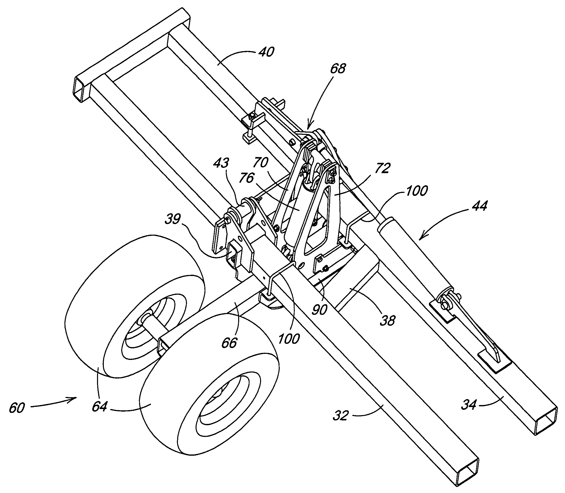
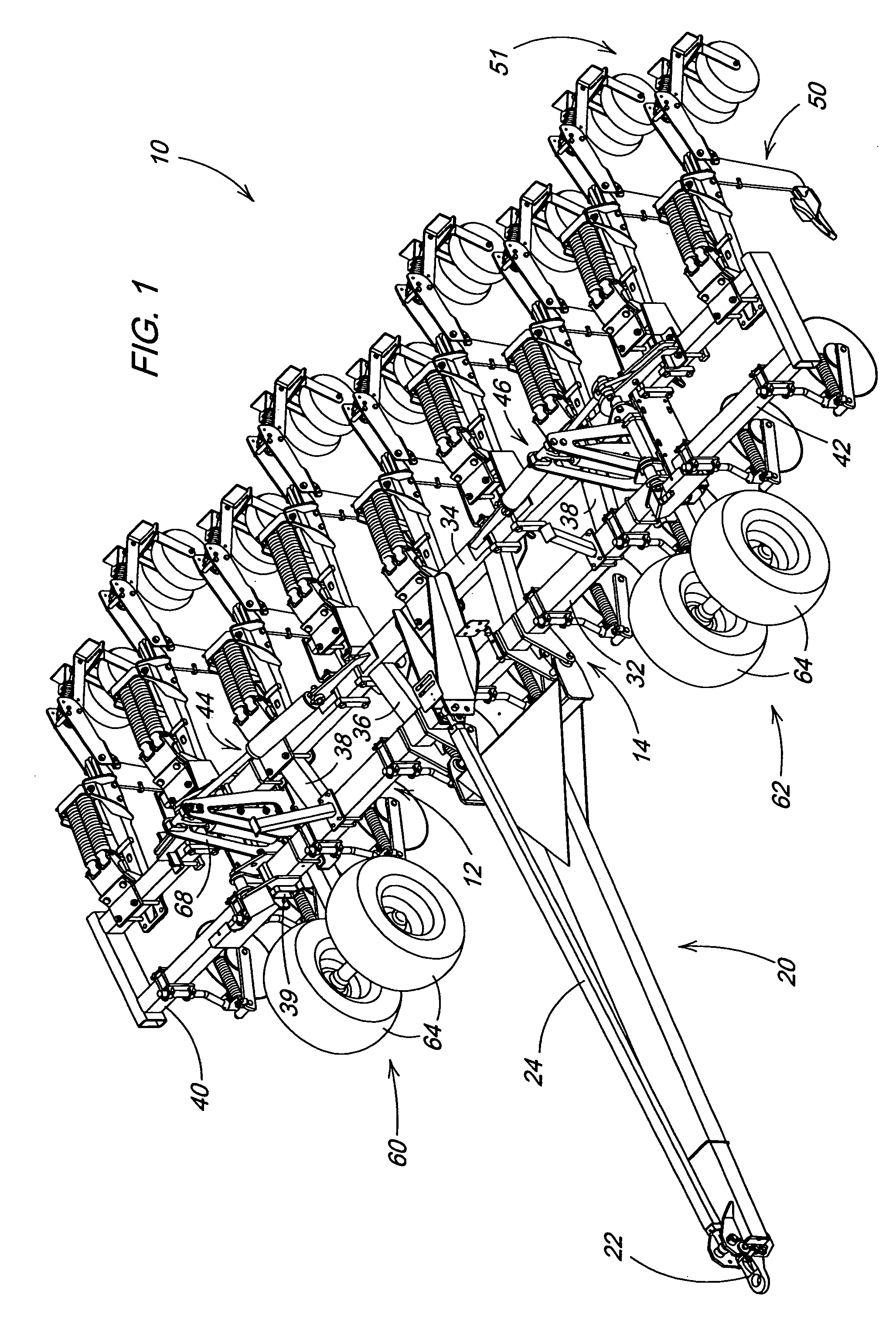
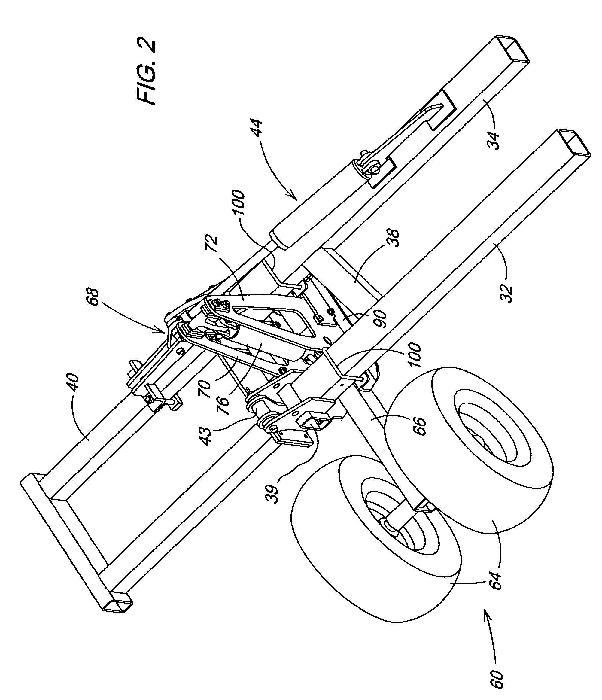
[0017]Referring now to FIG. 1, therein is shown an implement 10 such as a ripper or similar deep tillage implement having a main frame 12 and conventional three-point hitch structure 14 adapted for attachment to a three-point hitch (not shown) on a tractor or other towing vehicle. The implement 10 is shown with attachments for conversion to a towed implement. A hitch 20 is pivotally connected at a rearward end to the lower two attaching points of the three-point hitch structure 14. A standard towing connection 22 for attachment to the tractor drawbar is connected to the forward end of the hitch 20. A leveling link 24 extends between the towing connection 22 and the upper connection of the three point hitch structure 14 to provide a generally rigid but adjustable hitch connection to the frame 12.

[0018]The frame 12 as shown includes transversely extending front and rear frame members 32 and 34 connected by generally fore-and-aft extending frame members such as shown at 36 and 38 and b...


PUM


Abstract

A forward acting wheel arm for a drawn hitch includes a pivot point directly below the rear rank of the machine frame, and the wheels are rotated directly in front of the front rank during field operation. For transport, the wheels rotate below the front rank to minimize tongue-lightness. The need for stabilizer wheels on the rear of the machine is eliminated, and the wheel arms can be actuated with either series or parallel hydraulic cylinders. The wheel arm pivot and cylinder base end connection are both located on the same support plate, and the hydraulic cylinder force is internalized within the plate rather than being translated through the wheel module mounting hardware.

Description

FIELD OF THE INVENTION[0001]The present invention relates generally to agricultural implements such as rippers, and more specifically to wheel structure for such implements.BACKGROUND OF THE INVENTION[0002]For years, farmers have used various styles of rippers to fracture soil and improve crop yields. Recently, in-line rippers that can fracture soil without significantly disturbing the soil surface have gained popularity with farmers. In-line rippers have allowed operators to decrease subsequent tillage passes and improve residue retention of their fields to comply to strict erosion guidelines. Agricultural implements such as deep tillage rippers often are towed by a large four-wheel drive (4WD) tractor, especially if the implement is a larger unit with nine or more standards. A problem can arise when the operator desires to pull an integral ripper, which is normally mounted on a three point tractor hitch, since many 4WD tractors in the size range necessary are not equipped with suc...

Claims


Application Information

Patent Timeline
Patent Type & Authority Patents(United States)
IPC IPC(8): A01B63/00A01B5/00A01B63/22
CPCA01B63/22
Inventor STEINLAGE, DAVID LEEBIERL, JAMES FRANKLIN
Owner DEERE & CO
Why Eureka
Try Eureka