
Method and system for providing a phase-locked loop with reduced spurious tones

a phase-locked loop and spurious tones technology, applied in the field of phase-locked loops, can solve the problems of excessive emission power in adjacent channels, lock time, cost and power consumption, and degrade the performance of both transmitters and receivers,

Active Publication Date: 2006-05-02
NAT SEMICON CORP
View PDF13 Cites 29 Cited by
  • Summary
  • Abstract
  • Description
  • Claims
  • Application Information

AI Technical Summary

Benefits of technology

"The present invention relates to a method and system for reducing spurious tones in phase-locked loops (PLLs) used in wireless communication systems. The technical effect of the invention is to improve the performance of PLLs by reducing spurious tones, which can degrade performance and cause interference. The invention achieves this by introducing a sampling circuit that averages out phase errors and using a spur reduction circuit to prevent unwanted signals from affecting the PLL. The invention also includes a method for providing a phase-locked loop with reduced spurious tones."

Problems solved by technology

Key performance parameters of a PLL include phase noise, spurious response, lock time, cost and power consumption.
The spurious tones can degrade performance for both transmitters and receivers.
For transmitters using a local oscillator signal having high spurious tones, the transmitted signal can cause excessive emission power in adjacent channels.
First, non-ideal performance of analog circuitry, such as charge pump delay and amplitude mismatch, leakage current, oscillator gain non-linearity and the like, causes limit cycle during steady-state.
Second, fractional-N dividers, which are used in some cases to improve phase noise, can introduce phase disturbance to the PLL and result in spurious tones.
However, the conventional sampling technique suffers from saturation effect, which degrades system transient performance and requires a complex anti-saturation circuit to achieve a lock.

Method used


Image

  • Method and system for providing a phase-locked loop with reduced spurious tones
  • Method and system for providing a phase-locked loop with reduced spurious tones
  • Method and system for providing a phase-locked loop with reduced spurious tones

Examples


Embodiment Construction

[0016]FIGS. 1 through 6, discussed below, and the various embodiments used to describe the principles of the present invention in this patent document are by way of illustration only and should not be construed in any way to limit the scope of the invention. Those skilled in the art will understand that the principles of the present invention may be implemented in any suitably arranged phase-locked loop.

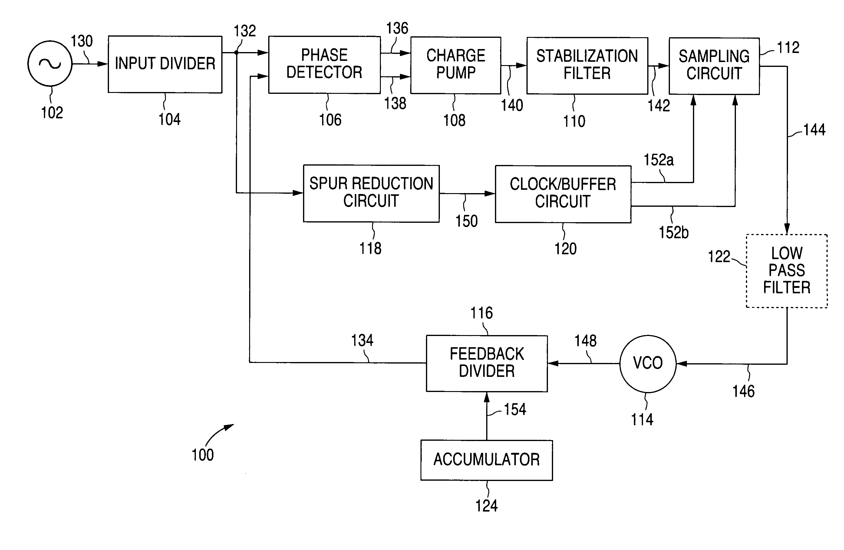
[0017]FIG. 1 is a block diagram illustrating a phase-locked loop (PLL) frequency synthesizer 100 with reduced spurious tones in accordance with one embodiment of the present invention. For one embodiment, the PLL frequency synthesizer 100 is operable to provide a local oscillator signal for a wireless transceiver or other suitable device based on an external clock signal. However, it will be understood that the PLL frequency synthesizer 100 may perform any suitable function without departing from the scope of the present invention.

[0018]The PLL frequency synthesizer 100 comprises a r...


PUM


Abstract

A method for providing a phase-locked loop with reduced spurious tones is provided that includes comparing a reference clock signal to an internal clock signal to generate a first signal. The first signal is sampled based on a sampling clock signal to generate a second signal. The sampling clock signal is reduced with respect to the reference clock signal. The internal clock signal is generated based on the second signal.

Description

TECHNICAL FIELD OF THE INVENTION[0001]The present invention relates generally to phase-locked loops and, more particularly, to a method and system for providing a phase-locked loop with reduced spurious tones.BACKGROUND OF THE INVENTION[0002]For wireless communication systems, local oscillator signals for frequency translation of received and / or transmitted signals are generated by phase-locked loop (PLL) frequency synthesizers. PLLs are also widely used in other electronic systems. For example, PLLs may be used as clock generators for high performance microprocessors.[0003]Key performance parameters of a PLL include phase noise, spurious response, lock time, cost and power consumption. The spurious tones can degrade performance for both transmitters and receivers. For transmitters using a local oscillator signal having high spurious tones, the transmitted signal can cause excessive emission power in adjacent channels. For receivers, the spurious tones of a local oscillator signal d...

Claims


Application Information

Patent Timeline
Patent Type & Authority Patents(United States)
IPC IPC(8): H03L7/06
CPCH03L7/1976H03L7/093
Inventor ZHANG, BENYONG
Owner NAT SEMICON CORP
Learn More