Optical element, optical scanner and image forming apparatus

an optical scanner and optical element technology, applied in the field of optical elements, optical scanners and image forming apparatuses, can solve the problems of inability to ensure the success of adjustment increase denaturation in the interior of molded plastics, and inability to adjust for other image heights

Inactive Publication Date: 2006-05-02
RICOH KK
View PDF14 Cites 37 Cited by
  • Summary
  • Abstract
  • Description
  • Claims
  • Application Information

AI Technical Summary

Benefits of technology

[0027]A more specific object of the present invention is to provide an optical element that can effectively correct misalignment of focused positions of optical spots due to a refractive index distribution in an optical scanner lens being the optical element and properly eliminate a deviation of pitches of the optical spots with respect to image heights, an optical scanner using the optical element, and an image forming apparatus using the optical scanner.
[0070]According to the above-mentioned inventions, it is possible to provide an image forming apparatus in which misalignment of focused positions of optical spots and an optical spot pitch deviation with respect to image heights are effectively corrected.

Problems solved by technology

Also, there arises denaturation in the interior of the molded plastics.
However, when an optical scanner lens in use has a refractive index distribution, the amount of the focused position misalignment is not constant for each image height.
Thus, even if a focused position corresponding to a certain image height is adjusted and a proper optical spot is obtained at that position, it is impossible to assure that the adjustment succeeds for other image heights.
In particular, when the diameter of an optical spot is narrowed down so that an image forming apparatus can create a higher-quality image, this problem becomes more significant.
If an optical scanner lens is designed without consideration of a refractive index distribution thereof, it is likely that the optical scanner lens cannot create a high-quality image because the optical spot diameter has wide variance with respect to the image heights.
Also, when an optical scanner lens with a refractive index distribution is used in a multi-beam optical scanner, the multi-beam optical scanner has a problem in that the multi-beam optical scanner has various pitches between optical spots on a scanned surface for image heights.
This problem is caused by the fact that each image height has a different horizontal magnification of image formation between an optical deflector and the scanned surface with respect to the sub-scanning direction.
For this problem, when the image heights have a large deviation of horizontal magnifications, there appears an irregularity in the recorded image.
In particular, when the pitches of the optical spots are made narrow so that an image forming apparatus can form a high-quality image, the irregularity becomes more significant.
As a result, it is impossible to avoid a considerably large correction of the metal pattern.
Thus, this conventional technique for forming the optical scanner lens has a difficulty with accurate correction.
However, when the diameter of an optical spot by the optical scanner lens is made smaller, it becomes difficult to maintain sufficient depth margin.
Furthermore, the optical scanner lens has additional problems in that the lens must be shaped and installed under quite severe error constraints thereof.
Adversely, these problems increase the fabrication cost.
In addition, the optical scanner lens is not preferable in terms of image quality.
In this conventional optical scanner, although the first optical system can correct the focused position misalignment for all image heights by an equal correction amount in an identical direction, it is impossible to individually correct the misalignment of each of the focused positions.
However, the focused positions are distinctly misaligned for the individual image heights due to the refractive index distribution.
In this case, it is impossible to obtain proper optical spots.
However, even if practical plastic lenses are formed in the fashion according to this disclosure, it is difficult to obtain proper optical spots.

Method used


Image

  • Optical element, optical scanner and image forming apparatus
  • Optical element, optical scanner and image forming apparatus
  • Optical element, optical scanner and image forming apparatus

Examples


first embodiment

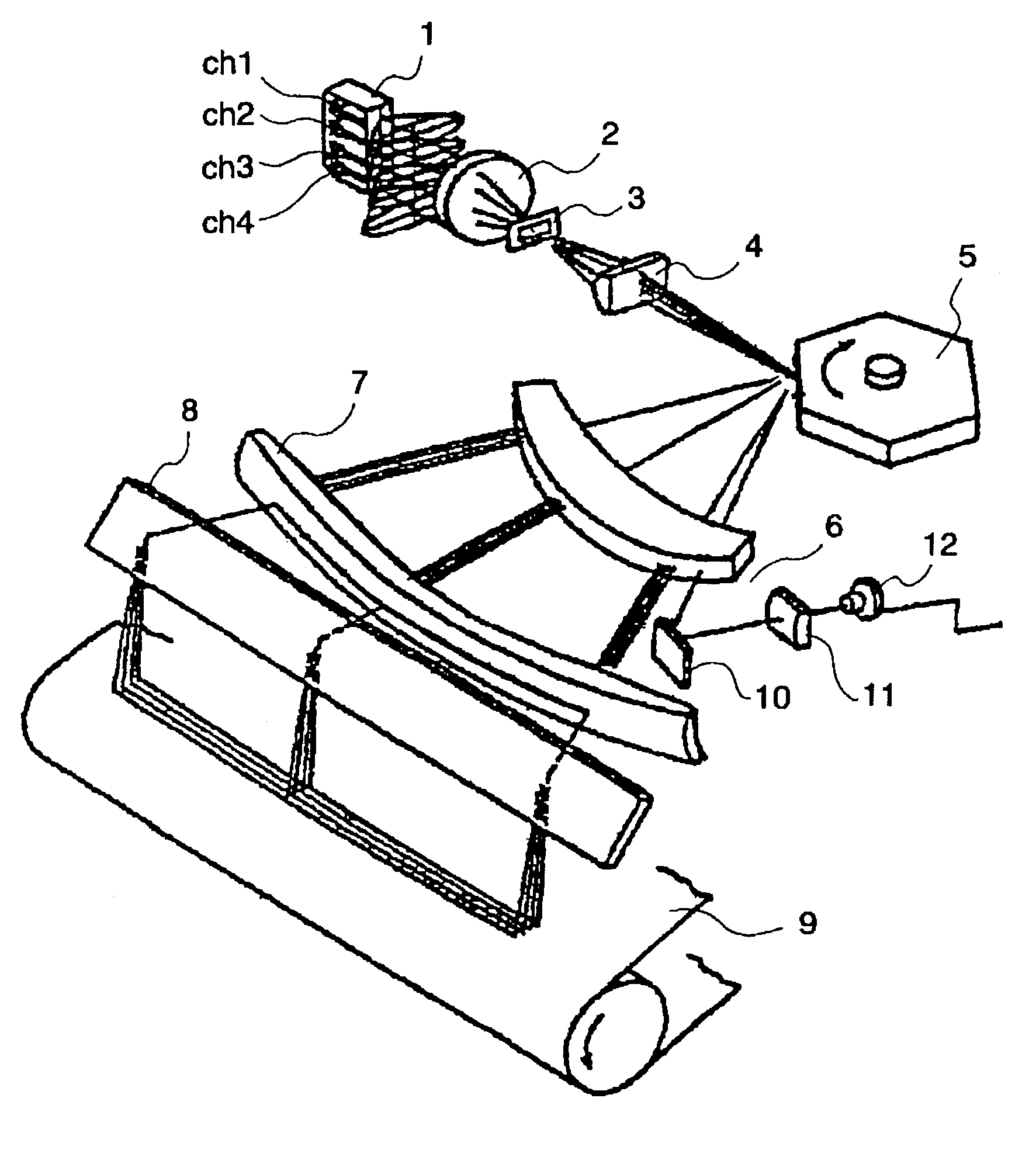
[0135]A description will now be given, with reference to FIG. 4 through FIG. 10, of an optical element according to the present invention.

[0136]FIG. 4 is a diagram for explaining an optical scanning system including an image forming scanner lens being the optical element according to the first embodiment. FIG. 5 and FIG. 6 are tables of coefficients of individual surfaces of the optical element without a refractive index distribution with respect to the main scanning direction and the sub-scanning direction. FIG. 7 is a table of coefficients of a refractive index distribution of the optical element with the refractive index distribution according to the first embodiment of the present invention. FIG. 8 and FIG. 9 are tables of individual surfaces of the optical element with the refractive index distribution according to the first embodiment with respect to the main scanning direction and the sub-scanning direction. FIGS. 10A through 10E show focused positions of the optical element ...

second embodiment

[0160]A description will now be given, with reference to FIG. 11 through FIG. 20, of an optical element according to the present invention.

[0161]FIG. 11 is a diagram for explaining an optical scanning system including an image forming scanner lens being the optical element according to the second embodiment. FIG. 12 through FIG. 15 show coefficients of optical elements having no refractive index distribution according to the second embodiment with respect to the main scanning direction and the sub-scanning direction for each surface thereof. FIG. 16 and FIG. 17 are tables of refractive index distributions of lenses 6 and 7, respectively, having the refractive index distributions according to the second embodiment. FIG. 18 and FIG. 19 are tables of coefficients of the lens 6 with respect to the main scanning direction and the sub-scanning direction for each surface thereof. FIGS. 20A through 20E show focused positions of the optical elements according to the second embodiment with re...

third embodiment

[0186]A description will now be given, with reference to FIG. 21 through FIG. 23, of an optical element according to the present invention.

[0187]FIG. 21 and FIG. 22 show coefficients of an optical element having a refractive index distribution according to the third embodiment with respect to the sub-scanning direction for each surface thereof. FIGS. 23A through 23C show focused positions of the optical element according to the third embodiment with respect to the main scanning direction and the sub-scanning direction.

[0188]An optical scanning system according to the third embodiment is fundamentally similar to the optical scanning system including an image forming scanner lens being the optical element according to the second embodiment. The optical scanning system differs from the optical scanning system according to the second embodiment in that coefficients of the lens 7 with respect to the sub-scanning direction are determined for each surface thereof so that misalignment of fo...


PUM


Abstract

An optical element can effectively correct misalignment of focused positions of optical spots and an optical spot pitch deviation with respect to image heights due to a refractive index distribution therein. The optical element includes a lens, which serves as an optical system in an optical scanner, is shaped in such a profile that misalignment of a focused position of the optical spot due to the refractive index distribution is corrected for image heights.

Description

BACKGROUND OF THE INVENTION[0001]1. Field of the Invention[0002]The present invention generally relates to an optical element, an optical scanner and an image forming apparatus, and more particularly to an optical element that can be preferably used as a writing system of a recording apparatus such as a digital copier, a laser printer and a laser facsimile, an optical scanner using the optical element, and an image forming apparatus using the optical scanner.[0003]2. Description of the Related Art[0004]In recent times, an optical scanner lens being an optical element used in an optical scanner has been fabricated through plastic molding. In order to form a lens through plastic molding, a hot melted plastic material is molded in accordance with a metal pattern and then is cooled in the metal pattern. In the cooling process, a peripheral portion of the metal pattern tends to be cooled earlier than a center portion thereof. As a result, there arises a nonuniform density distribution in...

Claims


Application Information

Patent Timeline
Patent Type & Authority Patents(United States)
IPC IPC(8): G02B26/08B41J2/44G02B3/06G02B13/00G02B17/08G02B26/10H04N1/028H04N1/113
CPCB41J2/473G02B26/0841
Inventor SAKAI, KOHJISUZUKI, SEIZOATSUUMI, HIROMICHI
Owner RICOH KK
Why Eureka
Try Eureka