High-power switchgear with cooling rib arrangement

a high-power switch and cooling rib technology, applied in the direction of electrical apparatus construction details, light and heating apparatus, laminated elements, etc., can solve the problems of severe heating of the generally tubular inner conductor, and achieve the effect of easy manufacturing of the cooling rib arrangement, good thermal contact, and simple manufacturing process

Active Publication Date: 2006-05-02
HITACHI ENERGY SWITZERLAND AG
View PDF8 Cites 6 Cited by
  • Summary
  • Abstract
  • Description
  • Claims
  • Application Information

AI Technical Summary

Benefits of technology

[0008]According to the invention, instead of arranging cooling ribs just on the hot inner conductor, cooling ribs are also arranged on the outer conductor which, per se, is considerably less hot than the inner conductor. This improves the effectiveness of the inner conductor cooling, without needing to modify the inner cooling itself. This is because the air within the outer conductor (housing) can emit its heat (which has been absorbed from the inner conductor) more effectively to the housing, since the housing can in turn emit its heat more effectively to the environmental air surrounding the housing, by means of the cooling rib arrangement. This allows very high rated currents to be carried in compliance with the Standards, even without using particularly complex, for example, active, inner conductor cooling. The switch pole encapsulation (housing) and thus the switch, may in this case remain compact. There is no need to enlarge the interior of the switch, which would also lead to more effective heat dissipation from the inner conductor. This makes it possible to produce a compact switch with small external dimensions.
[0023]The cooling is particularly effective if in each case two adjacent switch poles each have a cover, which is arranged above the respective inner conductor, with an incline which faces the respectively adjacent switch pole and is provided with cooling ribs of the cooling rib arrangement. In this advantageously symmetrical design, both switch poles profit from the active cooing resulting from the air flow between the switch poles.

Problems solved by technology

At the current levels mentioned, resistive losses lead to severe heating of the generally tubular inner conductor.
A switching device such as this has the disadvantage that, in order to achieve a high maximum permissible rated current for the switching device, a complex cooling arrangement must be fitted to the inner conductor in order to ensure that the specified maximum temperature is not exceeded.

Method used


Image

  • High-power switchgear with cooling rib arrangement
  • High-power switchgear with cooling rib arrangement
  • High-power switchgear with cooling rib arrangement

Examples


Embodiment Construction

[0005]The object of the invention is therefore to provide a high-power switch of the type mentioned initially, but which does not have the disadvantages mentioned above. One particular aim is to provide a switching device for high-rated currents and power levels, which do not exceed a specified maximum temperature when the rated current is flowing, and which is nevertheless compact and requires only a moderately complex cooling arrangement of the inner conductor.

[0006]This object is achieved by an apparatus and a method having the features of patent claim 1.

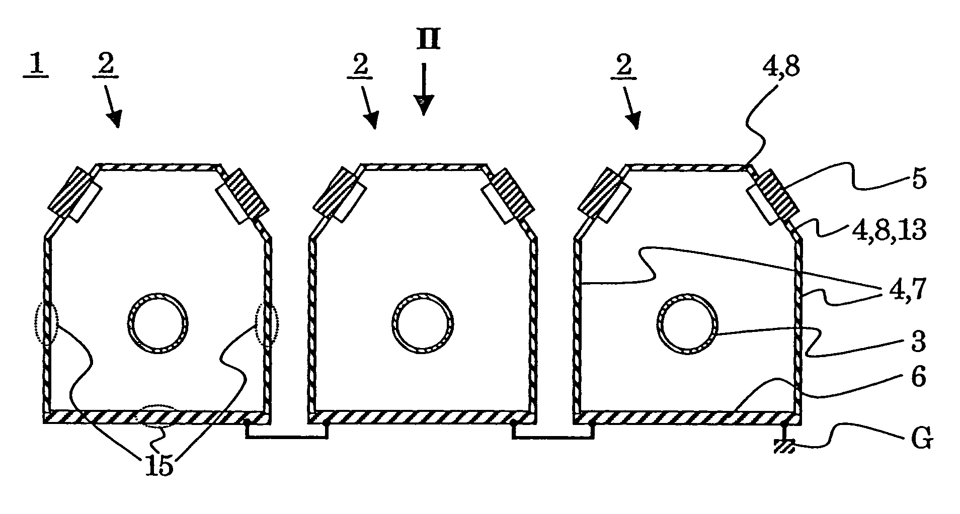
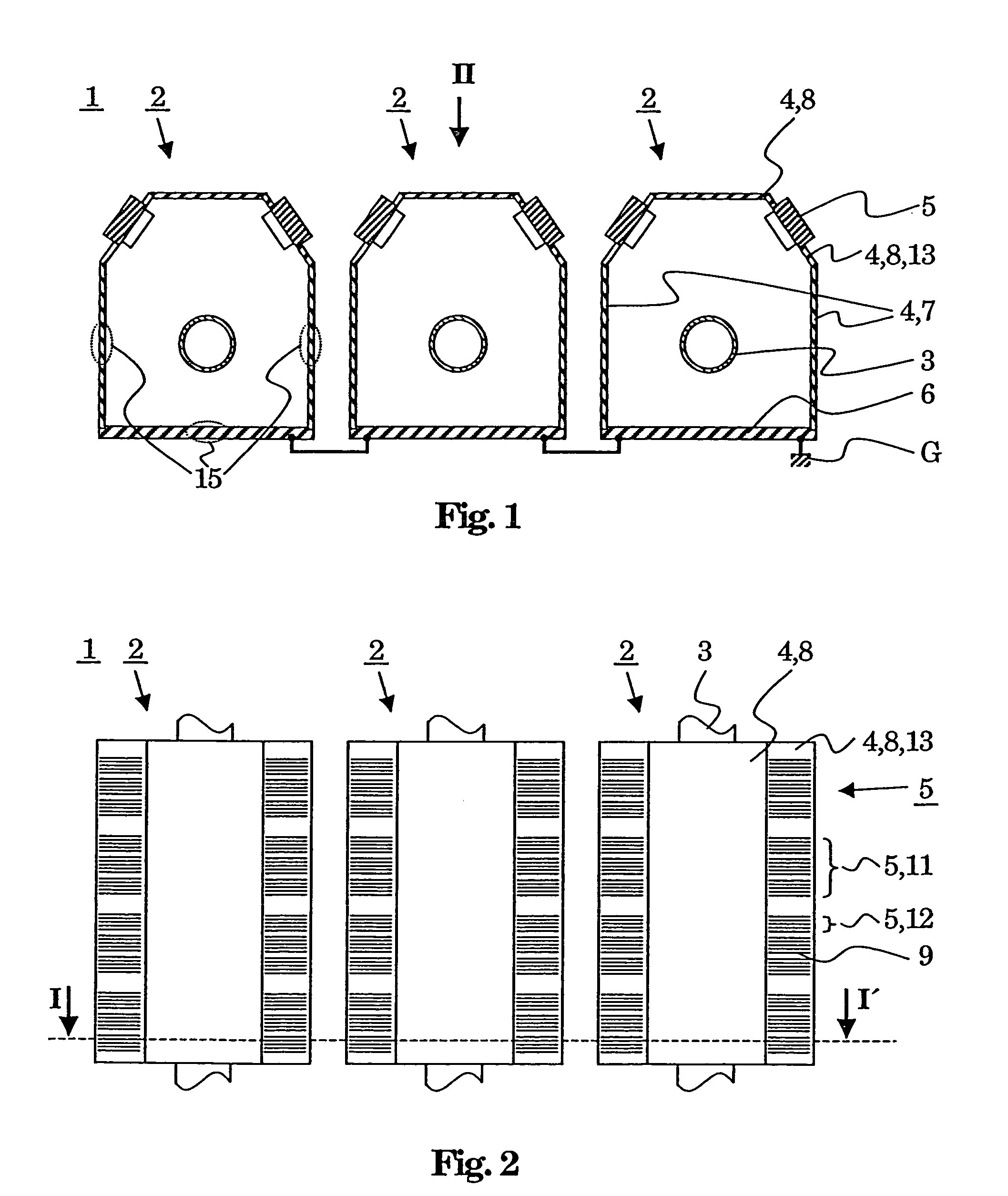
[0007]The high-power switch according to the invention with at least one switch pole for carrying and switching an electric current which flows in one current flow direction when the switch is in the closed state, with at least one switch pole containing an inner conductor which carries the current and containing an outer conductor which is connected to ground potential and carries a return current in the opposite direction to th...


PUM


Abstract

The high-power switch (1) according to the invention, with at least one switch pole (2) for guiding and switching an electric current which flows in one current flow direction when the switch is in the closed state, with the at least one switch pole (2) containing an inner conductor (3) which carries the current and containing an outer conductor (4) which is connected to ground potential (G) and carries a return current in the opposite direction to the current, with the outer conductor (4) being in the form of a housing (4) which surrounds the inner conductor (3), is characterized in that a cooling rib arrangement (5) which contains cooling ribs (9) is arranged on the outer conductor (4). At least some of the cooling ribs are advantageously arranged on a separate part of the housing (4), which is not the same as the part (15) of the housing (4) which is at a minimum distance from the inner conductor (3). The cooling rib arrangement (5) advantageously has cooling ribs both outside the housing (4) and inside the housing (4).

Description

TECHNICAL FIELD[0001]The invention relates to the field of high-power switch technologies, and in particular to a high-power switch as claimed in the precharacterizing clause of Patent claim 1.PRIOR ART[0002]High-power switches such as these (heavy current and / or high-voltage switches) such as self-blowout switches, gas-insulated switchgear assemblies, in particular generator switches, have been known for several decades and generally have in each case one switch pole, which is encapsulated, for each of three electrical phases. An inner conductor, which carries the current to be interrupted is located inside a switch pole such as this. The corresponding rated currents are typically between 6 kA and 40 kA at voltages of 1 kV to 50 kV. The inner conductor is surrounded by an outer conductor, which forms the encapsulation for the inner conductor, so that there is an area essentially without any field outside the outer conductor. The outer conductor, which is in the form of a housing, i...

Claims


Application Information

Patent Timeline
Patent Type & Authority Patents(United States)
IPC IPC(8): H05K7/20H01H33/56H01H9/52H01H33/00H02G5/10
CPCF28F3/048H01H9/52H02G5/10H01H33/002H01H2009/526
Inventor PLEINES, MARIANNEMAUROUX, JEAN-CLAUDELAKNER, MARTINSCHOENEMANN, THOMAS
Owner HITACHI ENERGY SWITZERLAND AG
Why Eureka
Try Eureka