Direct energy transfer converter

a converter and direct energy technology, applied in the direction of dc-dc conversion, power conversion system, metabolism disorder, etc., can solve the problems of not being able to achieve control, not being able to find a good compromise, and having a certain number of difficulties

Inactive Publication Date: 2006-05-02
ALCATEL LUCENT SAS
View PDF4 Cites 8 Cited by
  • Summary
  • Abstract
  • Description
  • Claims
  • Application Information

AI Technical Summary

Benefits of technology

[0014]This present invention aims at creating a direct energy transfer converter by self-regulated synchronous rectifier, of the active clamp type in particular, enabling the removal of both the conduction losses, due to

Problems solved by technology

The result is that this solution gives rise to a certain number of difficulties.
It can happen, in fact, that the maximum gate voltage of one of the two transistors is not sufficient to effect control.
Conversely, for high output voltages, above 10

Method used


Image

  • Direct energy transfer converter
  • Direct energy transfer converter
  • Direct energy transfer converter

Examples


first embodiment

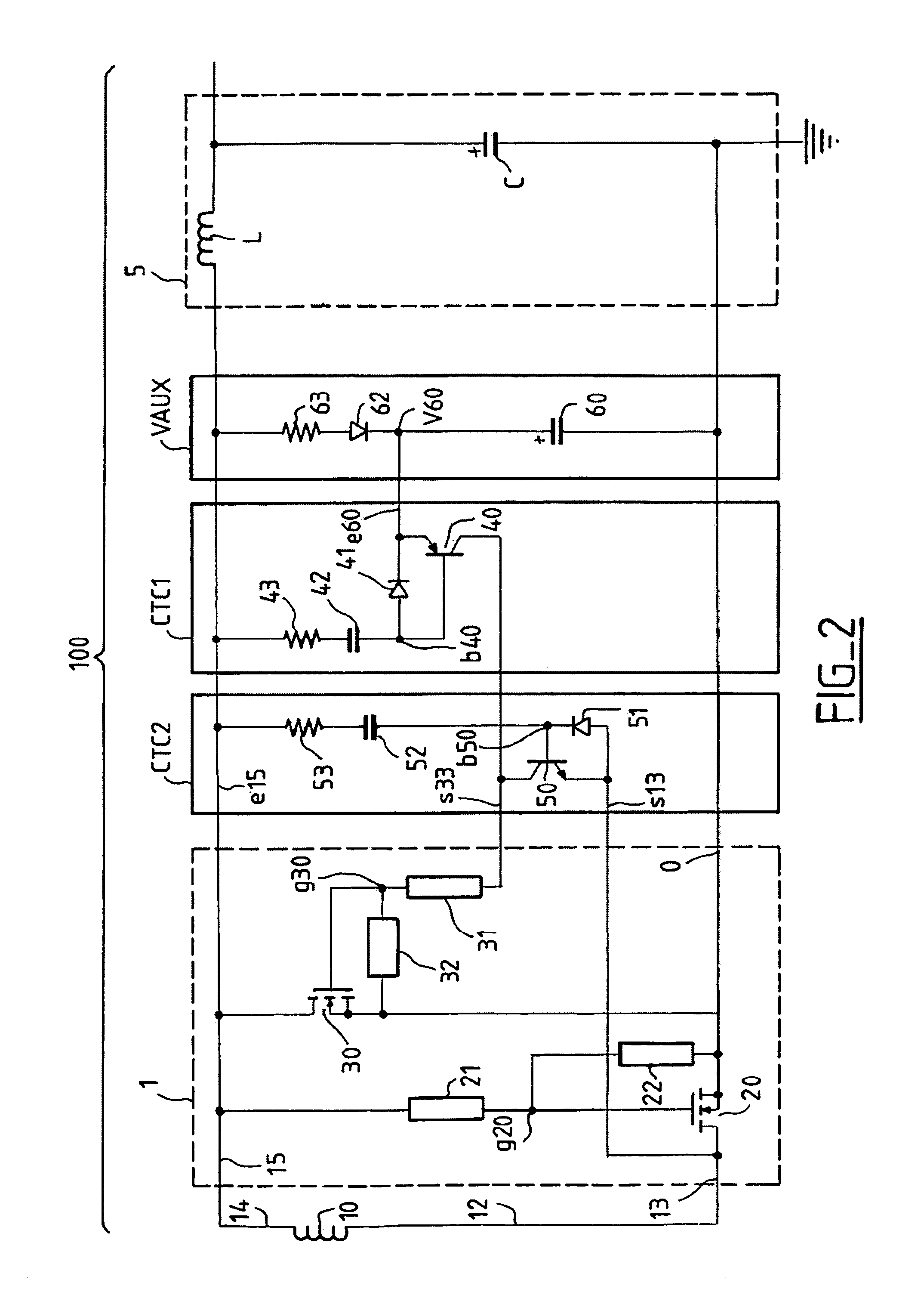
[0062]FIG. 2 represents the secondary part (100) of a direct energy transfer converter (100) according to the invention. Note that the primary part of the converter, which is not represented here, is implemented in a known manner, using a primary winding of a power transformer wired to an input voltage source, by means of switching elements mounted preferentially in direct energy transfer with active clamping.

[0063]Part 100 includes:[0064]a secondary winding (10) of a power transformer,[0065]a synchronous rectifier (1) of the direct energy transfer type,[0066]an LC output filter (5),[0067]means CTC1, called the first charge-transfer circuit,[0068]means CTC2, called the second charge-transfer circuit,[0069]an auxiliary voltage source (VAUX).

[0070]The synchronous rectifier (1) includes two secondary switches in the form of two MOSFET power transistors (20), (direct MOSFET) and (30) (freewheel MOSFET), which respectively implement the direct and freewheel phases of rectifier 1.

[0071]Th...

second embodiment

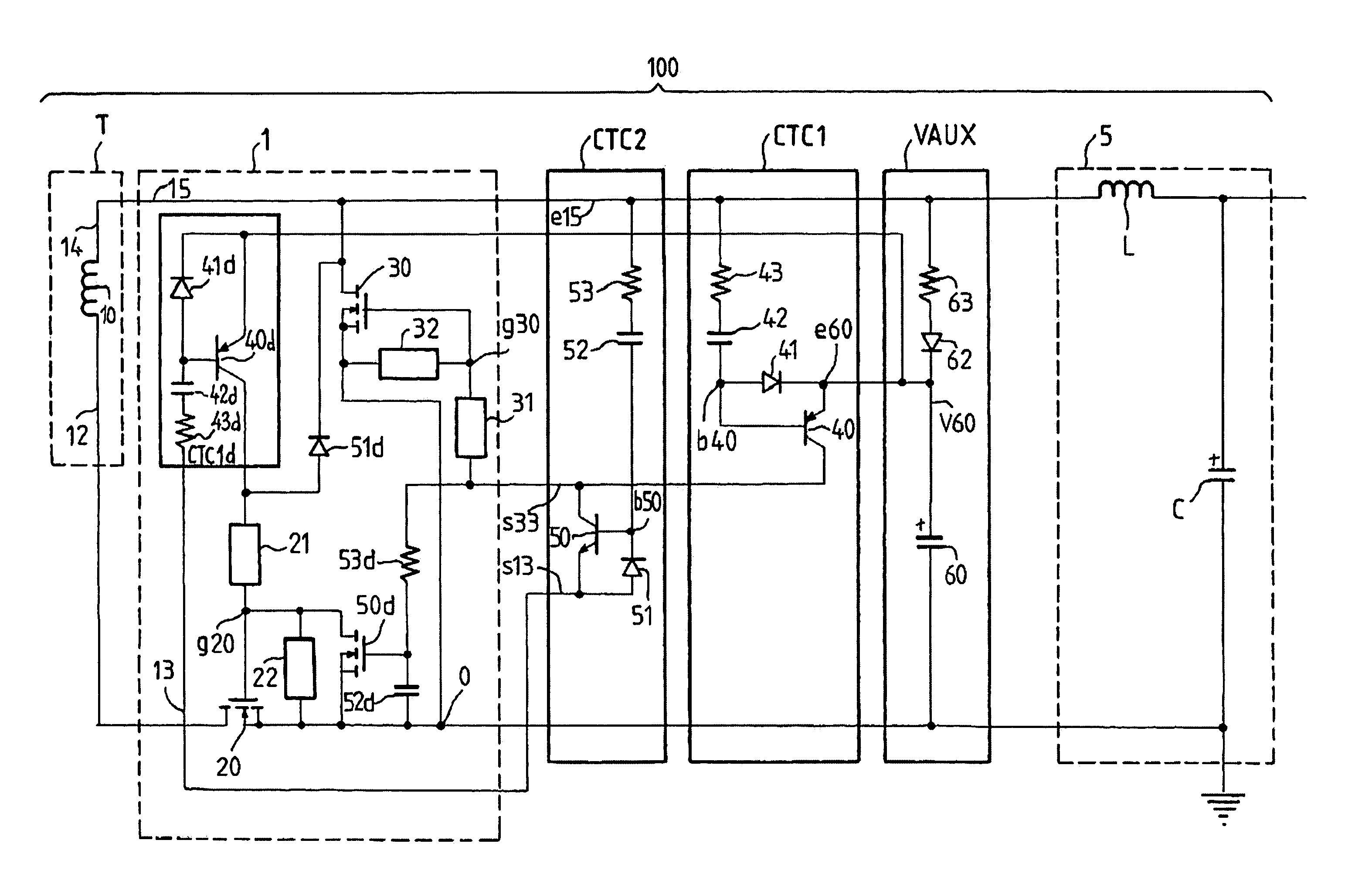
[0096]FIG. 4 schematically shows the secondary part (100) of a direct energy transfer converter according to the invention.

[0097]This secondary part (100) is identical to that represented on FIG. 2, except that it includes two other charge-transfer circuits (CTC1d and CTC2d), in order to generate the drive for the direct transistor (20), which depends only on the voltage source (VAUX).

[0098]The circuit CTC1d is created in an identical manner to circuit CTC1, and includes:[0099]a bipolar transistor (40d),[0100]a resistance (42d),[0101]a capacitance (42d),[0102]a diode (41d).

[0103]The circuit CTC2d includes:[0104]a MOSFET transistor (50d) called delay transistor,[0105]a capacitance (52d),[0106]a resistance (53d),[0107]a diode (51d).

[0108]The circuit CTC1 operates in an identical manner to circuit CTC1, and provides the charge for the gate of direct transistor 20.

[0109]The resistance 53d has one end connected to the gate of the freewheel transistor (30) via resistance 31, and the other...

third embodiment

[0112]FIG. 5 schematically shows the secondary part (10) of a direct energy-transfer converter, according to the invention.

[0113]The secondary part (100) here includes two power windings (10 and 10b) wired in phase opposition on rectifier transistors 20 and 30, and thus perform “full-wave” asymmetrical synchronous rectification with active clamping. Circuits CTC1, CTC2, CTC1d and CTC2d are created in an identical manner to the circuit shown on FIG. 4, but the synchronisation signals of these circuits change, since the signal available at point 15, the common point of then two windings (10 and 10b), is more or less continuous.

[0114]Thus the synchronisation signal for circuits CTC1 and CTC2 is taken from point 13b connecting the drain of transistor 30 to the end (14b) of winding 10b.

[0115]Likewise, the member 51d, assisting with cut-off of transistor 20, is connected to point 13b.

[0116]As for FIGS. 2 and 4, the charge-transfer circuits, CTC1, CTC2 and CTC1d, are synchronised by vari...


PUM


Abstract

The invention concerns a direct energy-transfer converter of the AC/AC or DC/DC type, including a self-regulated synchronous rectifier, in which the rectifier switches are controlled through one or more transformer windings. The converter includes a primary stage with at least one primary winding of a transformer and at least one controlled switch, with a secondary stage having at least one secondary winding (10) of the transformer, and a synchronous rectifier (1) with at least a first switch (20) which is self-regulated and conducting during the conducting phase of the controlled switch of the primary stage, known as the direct energy-transfer stage, and at least one secondary switch (30) which is self-regulated and conducting during the non-conducting phase of the controlled switch of the primary stage, known as the freewheel phase, and an output filter (5). Said converter also includes the means (CTC1) to render conducting said second switch (30) independently of the voltage at the terminals of the secondary winding (10) during said freewheel phase.

Description

BACKGROUND OF THE INVENTION[0001]The invention concerns a direct energy-transfer converter of the AC / AC or DC / DC type, consisting of a self-regulated synchronous rectifier. In the remainder of this document, the expression “synchronous rectifier” preferentially refers to a self-regulated synchronous rectifier, meaning a rectifier in which the rectifying switches are controlled over one or more transformer windings.[0002]Direct energy transfer conversion systems are known which include an input voltage source and at least one controlled primary switch, driving a transformer whose secondary is fitted with at least two power switches constituting a self-regulated synchronous rectifier. Said synchronous rectifier is mounted in cascade with a filter delivering a continuous controlled voltage into an application. In this type of conversion chain, the purpose of the rectifier is:[0003]to deliver to the application, through the filter, the energy transferred by the transformer during the co...

Claims


Application Information

Patent Timeline
IPC IPC(8): H02M3/335
CPCH02M3/335A61P3/00A61P9/00
Inventor DIALLO, ALMADIDIPUISIEUX, PHILIPPETHEREZE, JEAN-MARIE
Owner ALCATEL LUCENT SAS
Why Eureka
Try Eureka