PET device and image generating method for pet device

a technology of image generating method and pet device, which is applied in the field of pet apparatus and image generating method for pet apparatus, can solve the problems of deterioration of poor quantitativeness of reconstructed image, etc., and achieve excellent quantitativeness, good photon pair detection sensitivity and quantitativeness, and improve the resolution of reconstructed image.

Inactive Publication Date: 2006-05-02
HAMAMATSU PHOTONICS KK
View PDF19 Cites 15 Cited by
  • Summary
  • Abstract
  • Description
  • Claims
  • Application Information

AI Technical Summary

Benefits of technology

[0010]The present invention has been made to solve the above problems, and has as its object to provide a PET apparatus and an image generating method for the PET apparatus, which realize excellent quantitativeness by properly correcting the influence of scattered radiation while improving the resolution of a reconstructed image and keeping photon pair detection sensitivity high.
[0013]In the PET apparatus according to one aspect of the present invention, detection of coincidence counting information may be performed by a pair of photon detection elements in the same cylindrical detector included in the detecting section, a pair of photon detection elements respectively included in two adjacent cylindrical detectors depending on the sizes of each cylindrical detector and each slice collimator, or a pair of photon detection elements included in two separate cylindrical detectors. In other words, detection of coincidence counting information may be performed between two adjacent detector rings or between two separate detector rings as well as within the same detector ring (one layer of photon detection elements arrayed in the form of a ring in a direction parallel to the central axis). That is, the PET apparatus according to the present invention has an intermediate arrangement between a conventional two-dimensional PET apparatus and a conventional three-dimensional PET apparatus, and has sensitivity about several times higher than that of the conventional two-dimensional PET apparatus. The PET apparatus according to the present invention can therefore ensure good photon pair detection sensitivity and quantitativeness while improving the resolution of a reconstructed image.
[0014]In the PET apparatus according to one aspect of the present invention, in particular, the determining section determines whether a straight line connecting the light-receiving surfaces of a pair of photon detection elements which have simultaneously detected a photon pair crosses any one of the slice collimators. The first coincidence counting information accumulating section generates a signal sinogram on the basis of this determination result. The second coincidence counting information accumulating section generates a scatter sinogram. The image reconstructing section then corrects the influence of scattered components on the signal sinogram on the basis of the scatter sinogram, and reconstructs an image on the basis of the corrected signal sinogram. As described above, according to the present invention, scattered radiation is removed by a plurality of slice collimators, and the influence of scattered components on the signal sinogram is corrected on the basis of the scatter sinogram. This makes a reconstructed image have excellent quantitativeness.
[0015]In the PET apparatus according to one aspect of the present invention, each cylindrical detector is characterized by being formed by arraying two-dimensional position detectors, each for detecting the two-dimensional incident position of a photon on a light-receiving surface when the photon is incident on the light-receiving surface, on a predetermined plane in the form of a ring. This arrangement is suitable to improve the resolution of a reconstructed image by reducing the size of each photon detection element.
[0016]In addition, the PET apparatus according to one aspect of the present invention is characterized in that the apparatus further comprises moving means for moving the detecting section and the plurality of slice collimators together relative to an object to be examined which is placed in the measurement space in a direction parallel to the central axis, and the first and second coincidence counting information accumulating sections respectively acquire coincidence counting information during a period in which the detecting section and the plurality of slice collimators are moved relative to the object by the moving means, convert the coincidence counting information into information in a coordinate system fixed to the object, and accumulate the information. In this case, coincidence counting information is acquired during a period in which the detecting section and slice collimators are moved relative to the object in a direction parallel to the central axis by the moving means. The information is converted into information in a coordinate system fixed to the object and accumulated in the first coincidence counting information accumulating section or second coincidence counting information accumulating section. The image reconstructing section obtains a reconstructed image on the basis of the accumulated coincidence counting information (signal sinogram and scatter sinogram). With the above arrangement of the cylindrical detectors and slice collators, therefore, photon pairs can be detected with uniform sensitivity in the body axis direction of the object, and the quantitativeness of a reconstructed image can be made uniform.

Problems solved by technology

The above PET apparatuses, however, have the following problems.
In the case of the two-dimensional PET apparatus, however, the intervals between the respective slice collimators decrease with a reduction in the size of each photon detector, and hence the open area ratio decreases to result in a deterioration in photon pair detection sensitivity.
This, however, decreases the effect of shielding photons (gamma rays), i.e., the collimating effect, and hence scattered radiation cannot be efficiently removed, resulting in a deterioration in the quantitativeness of a reconstructed image.
As described above, however, since it is essentially difficult to eliminate the influence of scattered radiation in the three-dimensional PET apparatus, the quantitativeness of a reconstructed image is poor.

Method used


Image

  • PET device and image generating method for pet device
  • PET device and image generating method for pet device
  • PET device and image generating method for pet device

Examples


Embodiment Construction

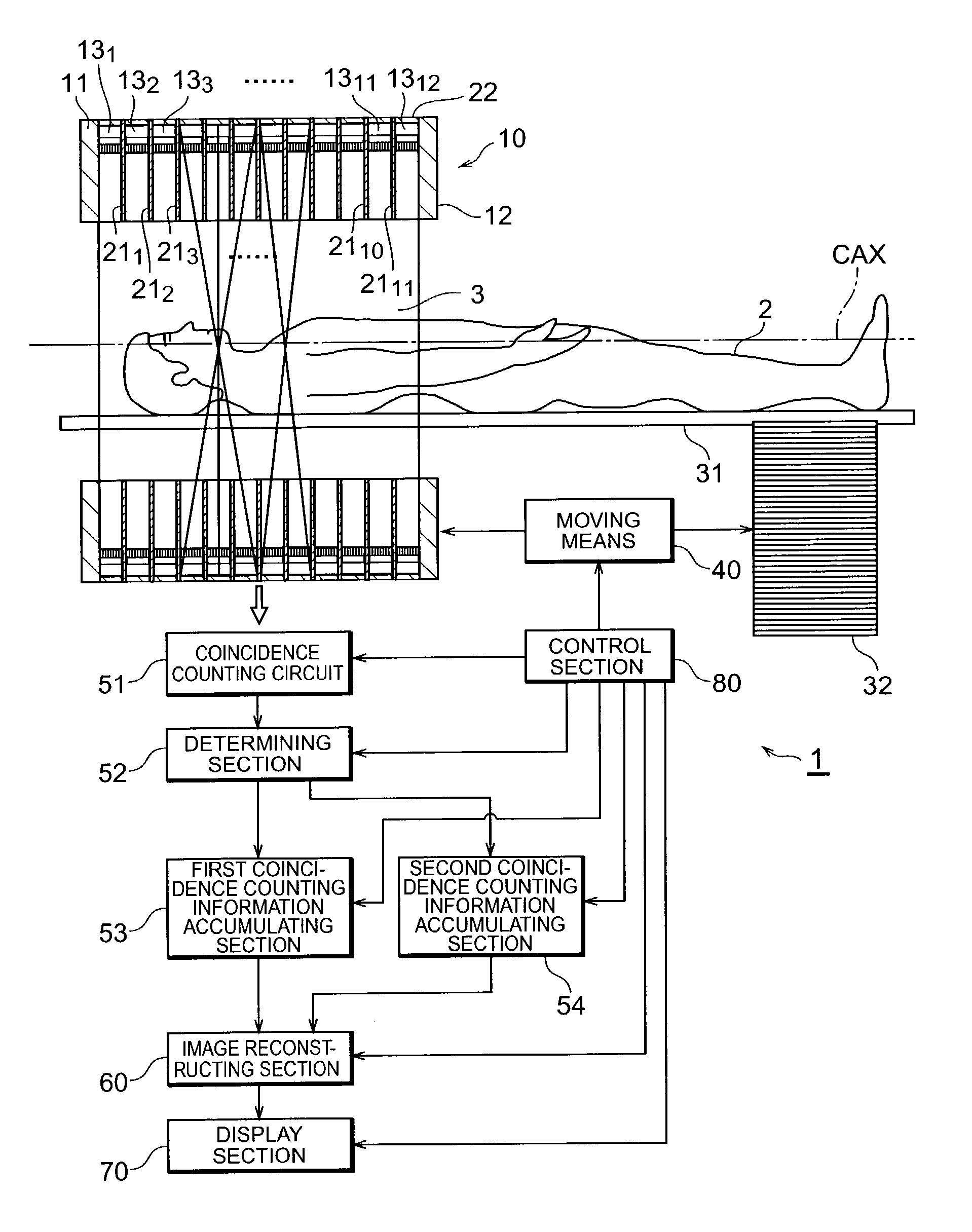
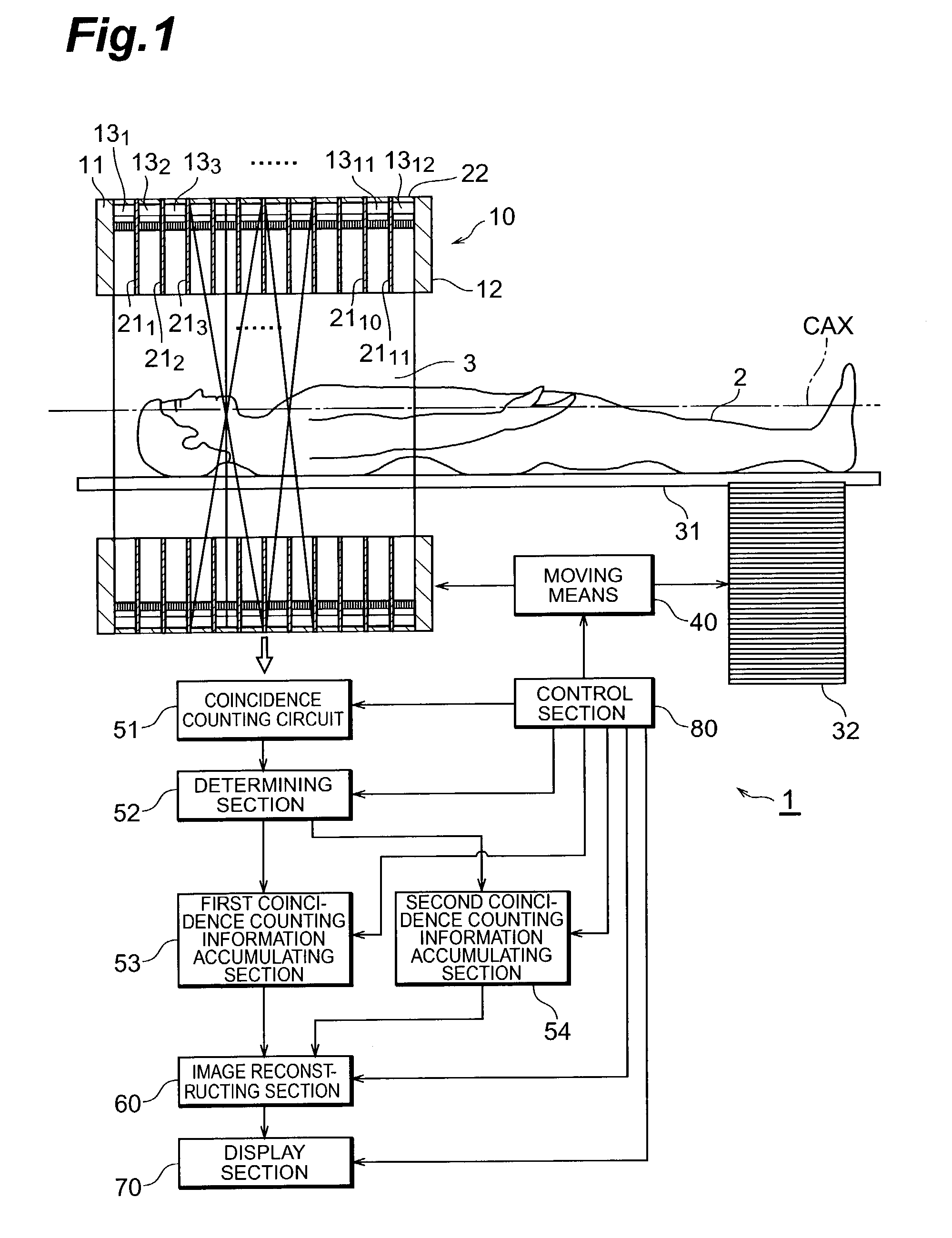
[0033]An embodiment of the present invention will be described in detail below with reference to the accompanying drawings. Note that the same reference numerals denote the same elements throughout the drawings, and a repetitive description will be avoided. Note that a PET apparatus 1 according to this embodiment to be described below incorporates all the elements and steps defined in the appended claims.

[0034]The arrangement of the PET apparatus 1 according to this embodiment will be described first with reference to FIGS. 1 to 5. FIG. 1 is a view showing the schematic arrangement of the PET apparatus 1 according to this embodiment. FIG. 1 shows cross-sections of a detecting section 10 and slice collimators 21 taken along a plane including a central axis CAX. The PET apparatus 1 according to the embodiment includes the detecting section 10, slice collimators 211 to 2111, a bed 31, a support base 32, a moving means 40, a coincidence counting circuit 51, a determining section 52, a f...


PUM


Abstract

A PET apparatus is provided, which ensures excellent quantitativeness by properly correcting the influence of scattered radiation while improving the resolution of a reconstructed image and keeping good photon pair detection sensitivity. A determining section 52 determines whether a straight line connecting the light-receiving surfaces 15b of a pair of photon detectors 15a which have simultaneously detected a photon pair crosses any one of slice collimators 21n. When it is determined that the straight line crosses none of the slice collimators 21n, the corresponding coincidence counting information is accumulated by a first coincidence counting information storage section 53 to generate a signal sinogram. When it is determined that the straight line crosses one of the slice collimators 21n, the corresponding coincidence counting information is accumulated by a second coincidence counting information storage section 54 to generate a scatter sinogram. An image reconstructing section 60 corrects the influence of scattered components on the signal sinogram on the basis of the scattered sinogram, and reconstructs an image on the basis of the corrected signal sinogram.

Description

TECHNICAL FIELD[0001]The present invention relates to a PET apparatus and an image generating method for the PET apparatus which can image the behavior of a substance marked by a positron emission isotope (RI radiation source).BACKGROUND ART[0002]A PET (Positron Emission Tomography) apparatus is an apparatus which can image the behavior of a trace substance in an object (living body) to be examined by detecting a pair of 511 keV photons (gamma rays) which fly in opposite directions upon electron-positron pair annihilation in the object irradiated with RI radiation. The PET apparatus includes a detecting section having many small photon detectors arrayed around a measurement space in which an object to be examined is placed. This apparatus detects a photon pair generated upon electron-positron pair annihilation by coincidence counting, accumulates the coincidence counting information, and reconstructs an image representing the spatial distribution of occurrence frequencies of photon ...

Claims


Application Information

Patent Timeline
Patent Type & Authority Patents(United States)
IPC IPC(8): G06K9/00G01T1/164G01T1/161G01T1/29
CPCA61B6/037G01T1/2985
Inventor TANAKA, EIICHIYAMASHITA, TAKAJI
Owner HAMAMATSU PHOTONICS KK
Why Eureka
Try Eureka