AGC amplifier circuit for use in a digital satellite broadcast receiver apparatus

a digital satellite broadcast receiver and amplifier circuit technology, applied in the direction of gain control, phase-modulated carrier system, digital transmission, etc., can solve the problem of reducing the characteristics of the amplifier circuit by 2 db, the limitation of reducing the characteristics, and the im characteristics are degraded by 2 db, so as to minimize the fluctuations in the minimum gain gbbmin and the effect of reducing the fluctuations in the gain

Inactive Publication Date: 2006-05-02
SHARP KK
View PDF8 Cites 21 Cited by
  • Summary
  • Abstract
  • Description
  • Claims
  • Application Information

AI Technical Summary

Benefits of technology

[0028]An object of the present invention is to provide an AGC amplifier circuit and a receiver apparatus with minimum fluctuations in their overall characteristics.
[0031]The gain of the fixed-gain amplifier 2 is not affected by the AGC voltage Vagc, and this makes it possible to minimize fluctuations in the minimum gain GBBmin of the BB AGC amplifier circuit 21 simply by minimizing fluctuations in the gain of the fixed-gain amplifier 2 resulting from fluctuations in the operating temperature and voltage thereof and variations in the constants of the circuit elements thereof.

Problems solved by technology

Specifically, if the input level varies by 1 dB, the undesirable third-order IM component varies by 3 dB, which causes degradation by 2 dB of IM characteristics.
That is, a small fluctuation in the gain control voltage Vagc2 results in a large fluctuation in the gain.
However, in realizing these circuits as an integrated circuit, there is a limit to reducing fluctuations in characteristics resulting from variations in the constants of the circuit elements within each circuit block.
Thus, in realizing the desired function by combining a plurality of circuits, it is highly difficult to reduce fluctuations in the overall characteristics.

Method used


Image

  • AGC amplifier circuit for use in a digital satellite broadcast receiver apparatus
  • AGC amplifier circuit for use in a digital satellite broadcast receiver apparatus
  • AGC amplifier circuit for use in a digital satellite broadcast receiver apparatus

Examples


Embodiment Construction

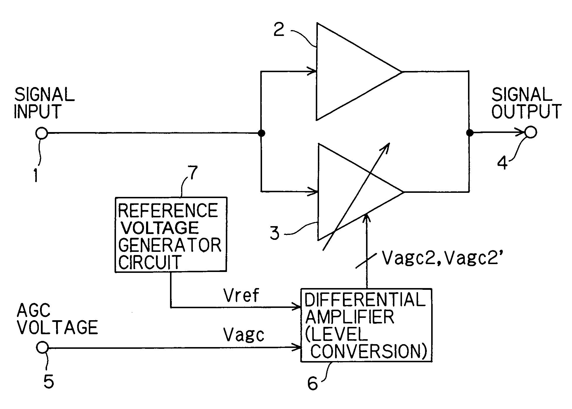
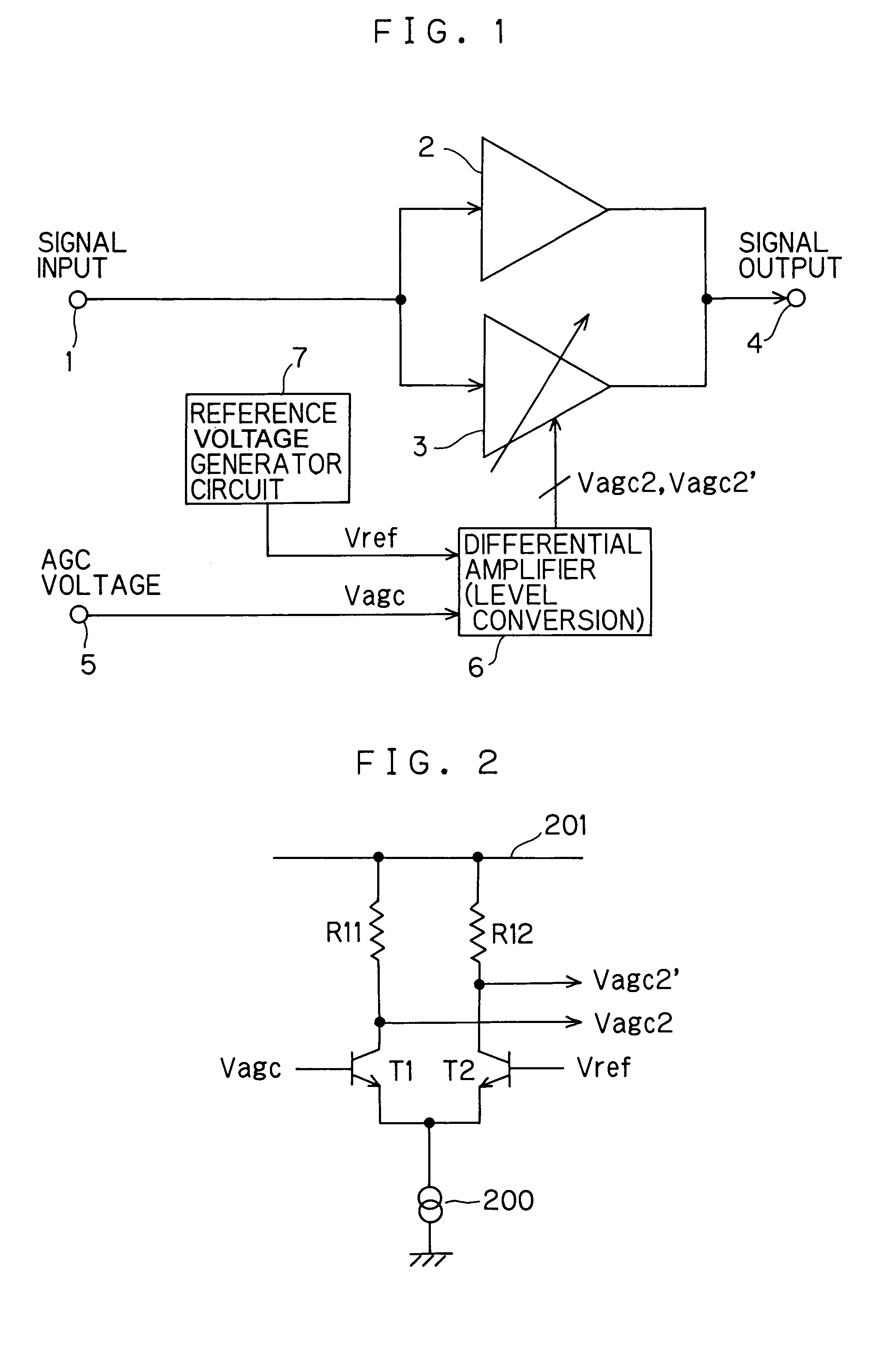
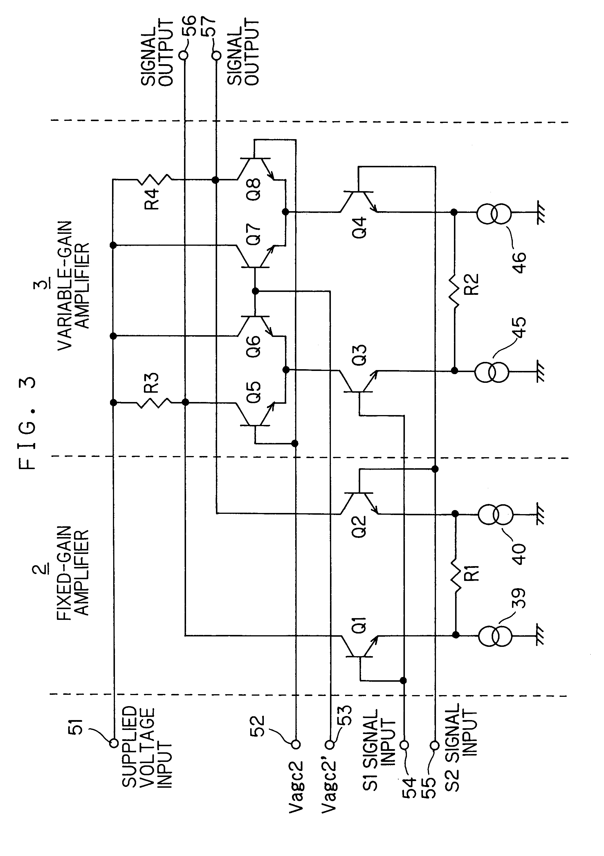
[0044]FIG. 1 shows an AGC amplifier circuit embodying the invention. This AGC amplifier circuit is used, for example, as the BB AGC amplifier circuit 21 described previously. In FIG. 1, reference numeral 1 represents a signal input terminal, reference numeral 2 represents a fixed-gain amplifier of which the gain does not depend on an AGC voltage, reference numeral 3 represents a variable-gain amplifier, reference numeral 4 represents a signal output terminal, reference numeral 5 represents an AGC voltage input terminal, reference numeral 6 represents a differential amplifier for level conversion, and reference numeral 7 represents a reference voltage generator circuit. Here, the reference voltage generator circuit 7 is configured as a common band-gap constant-voltage circuit so as to be hardly susceptible to fluctuations in the ambient temperature and in the supplied voltage, and thus supplies a reference voltage Vref stably. The signal fed in via the terminal 1 is fed to the fixed-...


PUM


Abstract

An AGC amplifier circuit has a fixed-gain amplifier, of which the gain is not controlled by an AGC voltage, and a variable-gain amplifier, of which the gain is controlled by the AGC voltage, that are connected in parallel. When the AGC voltage is within a predetermined voltage range, the overall gain of the AGC amplifier circuit is varied by the variable-gain amplifier; however, when the AGC voltage is outside the predetermined voltage range, the overall gain is kept constant by the fixed-gain amplifier. The minimum gain of the AGC amplifier circuit is set to be equal to the gain of the fixed-gain amplifier.

Description

BACKGROUND OF THE INVENTION[0001]1. Field of the Invention[0002]The present invention relates to an amplifier circuit for use in a digital satellite broadcast receiver apparatus.[0003]2. Description of the Prior Art[0004]As an example of the configuration of a digital satellite broadcast receiver apparatus, FIG. 5 shows a block diagram of a direct-conversion receiver apparatus. The circuit shown in FIG. 5 is divided roughly into three blocks, namely an antenna section 32, a tuner section 33, and a digital signal processing section 34. In the antenna section 32, a reception antenna 14 receives a satellite broadcast digital signal transmitted in a 12 GHz frequency band from a stationary satellite located up in the sky.[0005]An LNB (low-noise amplifier and block down converter) fitted directly underneath, the reception antenna 14 amplifies the faint satellite broadcast digital signal received by the reception antenna 14 with a low-noise, high-gain amplifier, and converts the signal, in...

Claims


Application Information

Patent Timeline
Patent Type & Authority Patents(United States)
IPC IPC(8): H04B1/06H03G3/20H03F3/45H03F3/68H03G1/00H03G3/30H04B1/10H04B1/16H04B1/30H04L27/22
CPCH03F3/45085H03F3/68H04B1/109H03G1/0023H03F2200/372
Inventor ISODA, HIROSHI
Owner SHARP KK
Why Eureka
Try Eureka