Switchable gain amplifier

a gain amplifier and switchable technology, applied in the field of amplifiers, can solve the problems of large variation in the signal strength of the radio frequency (rf) signals received by the wireless communication device, additional material costs, and additional area on the circuit board of the wireless devi

Inactive Publication Date: 2006-05-02
SKYWORKS SOLUTIONS INC
View PDF33 Cites 27 Cited by
  • Summary
  • Abstract
  • Description
  • Claims
  • Application Information

AI Technical Summary

Benefits of technology

[0009]A switchable gain amplifier for use in mobile communications devices is achieved by using two amplifier stages connected in parallel. The first amplifier stage has a first gain and the second amplifier stage has a second gain which is less than the first gain. A gain controller coupled to the first amplifier stage and to the second amplifier stage enables one of the amplifier stages at a given time. The gain controller may include a gain control input, a current switch, and first and second bias current circuits responsive to the gain control input, and may include a first current enable output and a second current enable output to control the first bias current circuit and the second bias current circuit respectively. In one embodiment, the second gain may be about 0 dBs, and the first gain may exceed the second gain by at least 10 dBs.

Problems solved by technology

The mobile use of a wireless communication devices, however, may result in large variations in signal strength of the radio frequency (RF) signals received by the wireless communication devices.
A discrete attenuator, however, has the disadvantages of additional material costs, additional area required on the circuit board of the wireless device, and additional load on the input of the LNA even when the attenuator is switched out, thereby degrading noise performance.
Simply switching off the LNA also has a drawback.
Switching off or bypassing the LNA when a strong signal is present would not allow the dual use of the driver for the downconverter as a current sink for the LNA.

Method used


Image

  • Switchable gain amplifier
  • Switchable gain amplifier
  • Switchable gain amplifier

Examples


Embodiment Construction

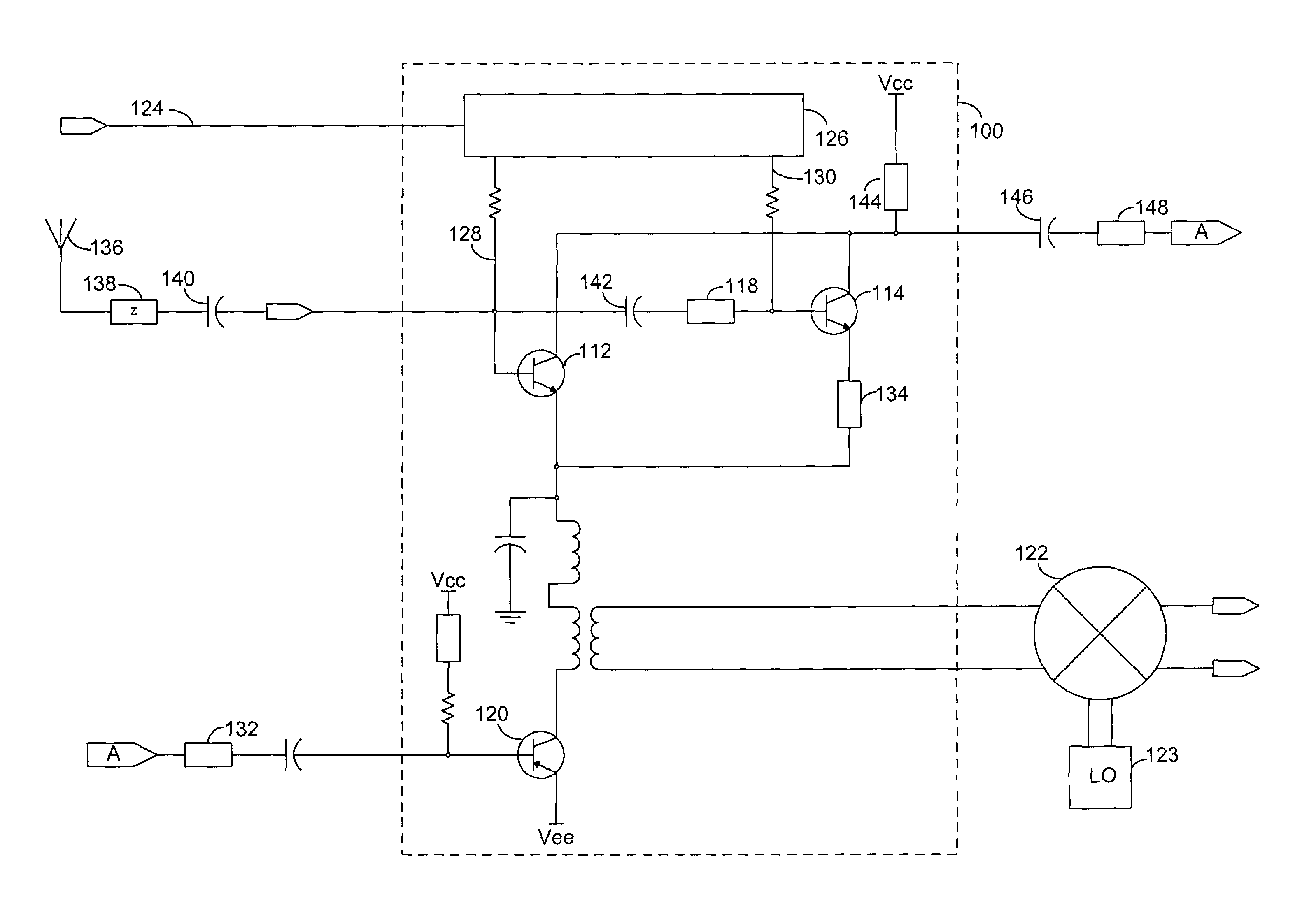
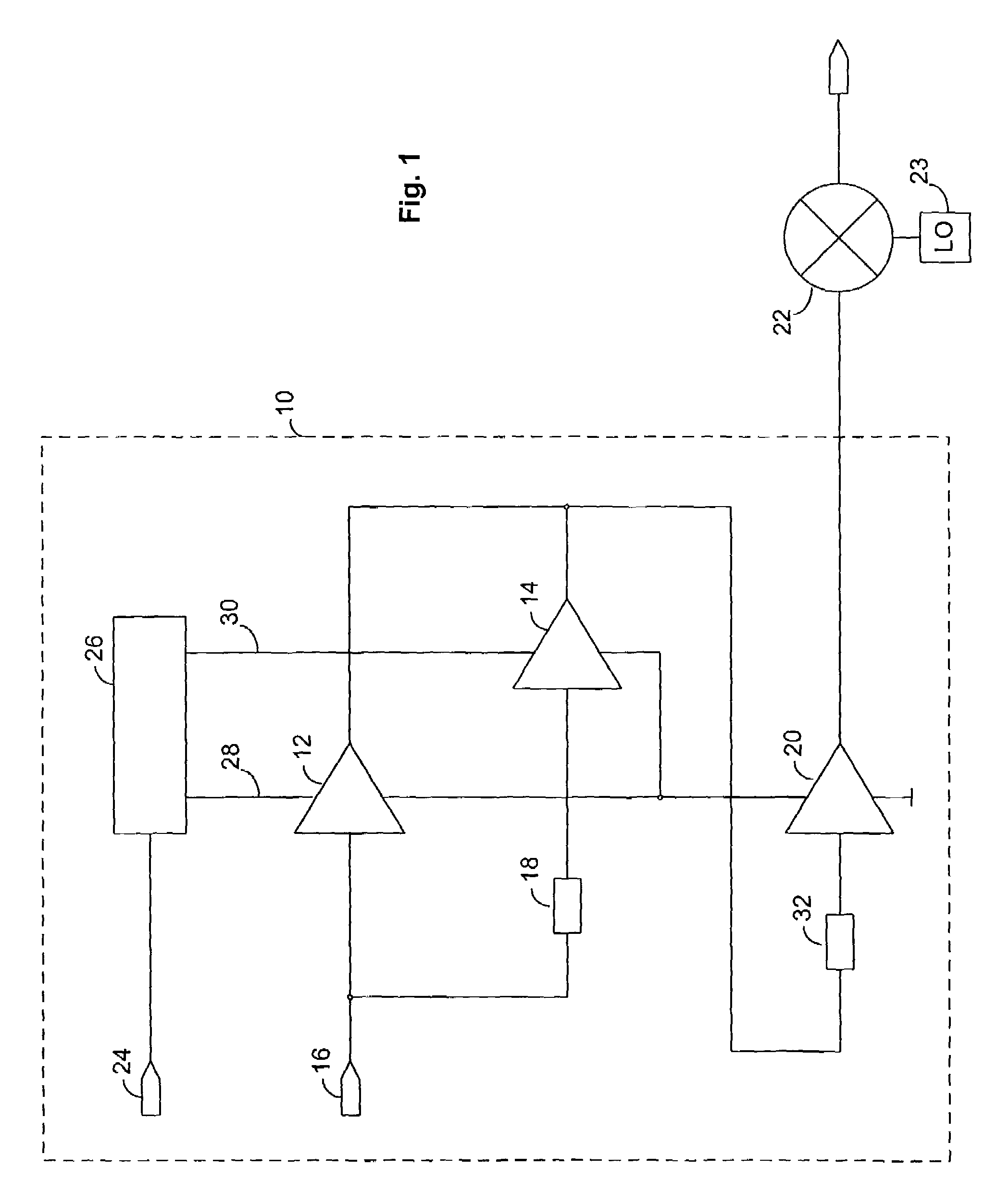
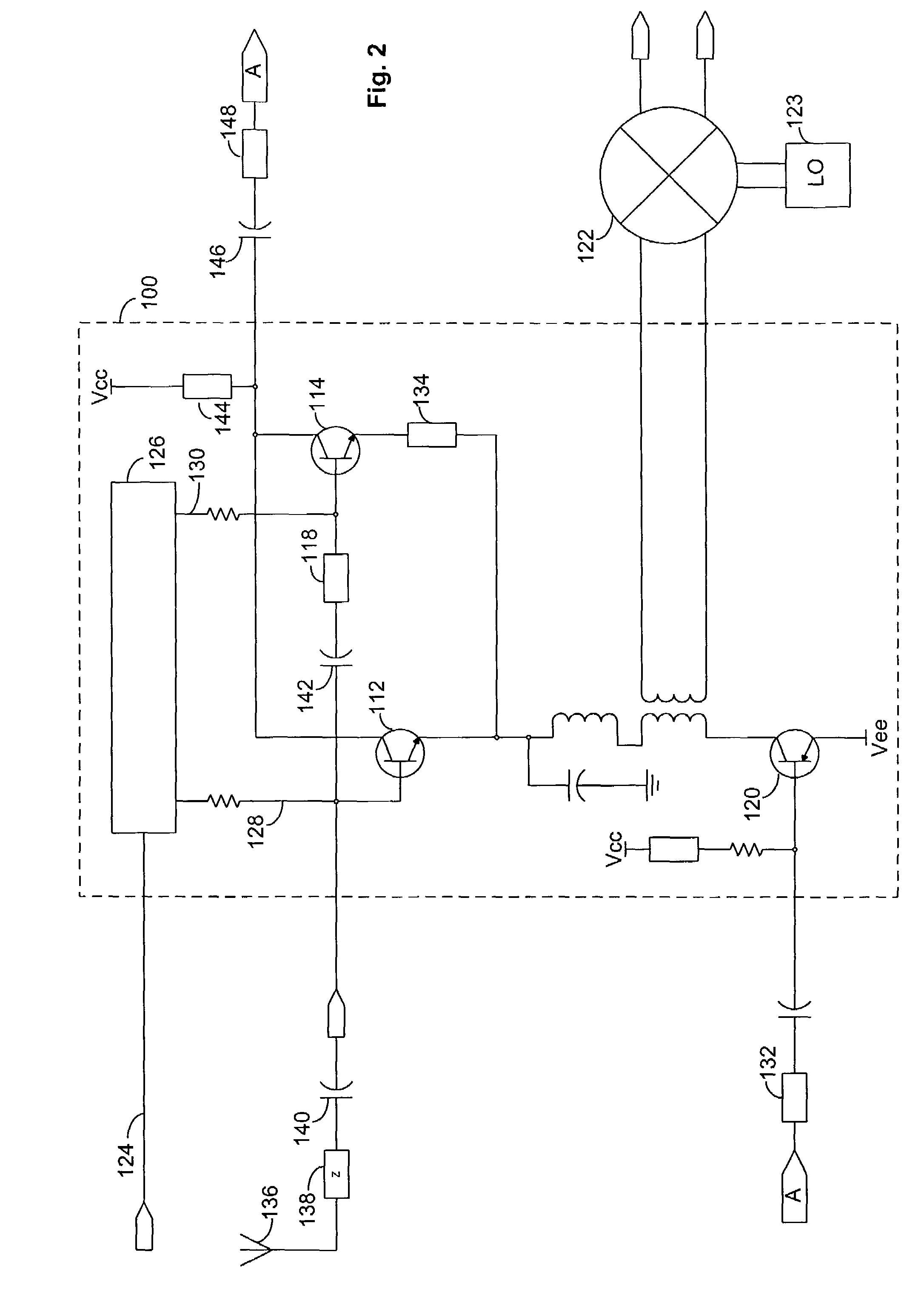
[0016]FIG. 1 is a circuit block diagram illustrating an embodiment of a switchable gain low noise amplifier 10. The switchable gain low noise amplifier 10 comprises a first amplifier stage 12 and a second amplifier stage 14. The amplifier stages 12, 14 may be any amplifier with characteristics suitable for the desired application. The first amplifier stage 12 and second amplifier stage 14 are optimized to provide the desired power gain, noise figure and linearity, without requiring the load of a discrete attenuator. The first and second amplifier stages may be, but are not required to be, substantially physically identical. Differences between the first amplifier stage and the second amplifier stage may include power gain, linearity, and noise performance. In the embodiment illustrated in FIG. 1, the first amplifier stage 12 may be configured for a gain of about 13.5 dBs, and the second amplifier stage 14 may be configured for a gain of about 0 dBs, however, these gain values are fo...


PUM


Abstract

A switchable gain amplifier for use in mobile communications devices is provided, having a first amplifier stage having a first gain, a second amplifier stage connected in parallel with the first amplifier stage. The first and second amplifier stage have different gains and a gain controller, connected to the first amplifier stage and to the second amplifier stage, enables only one of the amplifier stages at a time.

Description

BACKGROUND OF THE INVENTION[0001]1. Field of the Invention[0002]This invention relates generally to the field of amplifiers and more particularly to switchable gain amplifiers.[0003]2. Related Art[0004]One of the most readily appreciated benefits of wireless communications is the mobility afforded the user of wireless communications. Mobile handsets having wireless telephone technology may be used in a variety of environments, for example, indoors, outside, or while travelling in an automobile or other vehicle.[0005]The mobile use of a wireless communication devices, however, may result in large variations in signal strength of the radio frequency (RF) signals received by the wireless communication devices. Depending upon where the mobile handset is in relation to a basestation, and what obstacles may be in the transmission path, the received RF signal may be anywhere within a very wide range of signal strengths at the antenna. When the signal is relatively weak, more amplification ...

Claims


Application Information

Patent Timeline
Patent Type & Authority Patents(United States)
IPC IPC(8): H04B1/06H03F3/72H03G1/00H04B1/16
CPCH03F3/72H04B1/16H03G1/0088H03F2200/294H03F2203/7236H03F2200/372H03F1/14H03G3/30
Inventor YATES, DAVID L.
Owner SKYWORKS SOLUTIONS INC
Why Eureka
Try Eureka