Method and apparatus for splitting a logical block

a logical block and block technology, applied in the field of mass digital data storage systems, can solve the problems of time-consuming and relative significant overhead, and achieve the effect of improving the performance of the overall system

Inactive Publication Date: 2006-05-02
SANDISK TECH LLC
View PDF32 Cites 85 Cited by
  • Summary
  • Abstract
  • Description
  • Claims
  • Application Information

AI Technical Summary

Benefits of technology

[0013]By splitting a logical block which is generally accessed less than 4 pages at a time into a plurality of physical blocks, when an overall flash memory system is formatted, each of the physical blocks associated with the logical block is substantially only partially full, as a portion of the logical block data may be written into each of a plurality of physical blocks. When each physical block is substantially only partially full, each physical block essentially has available pages into which updates may be written. As such, the need to rewrite a full physical block into an empty physical block is reduced by the ability to write information pertaining to updates into available pages of a physical block. It is only after the available pages are all filled that the physical block may need to be rewritten. As such, by reducing the number of times physical blocks are copied into other physical blocks and erased, the performance of an overall system may be improved.

Problems solved by technology

In general, copying the entire contents of a physical block any time a single page is to be updated within the block utilizes a relatively significant amount of overhead, and may prove to be time-consuming.

Method used


Image

  • Method and apparatus for splitting a logical block
  • Method and apparatus for splitting a logical block
  • Method and apparatus for splitting a logical block

Examples


Embodiment Construction

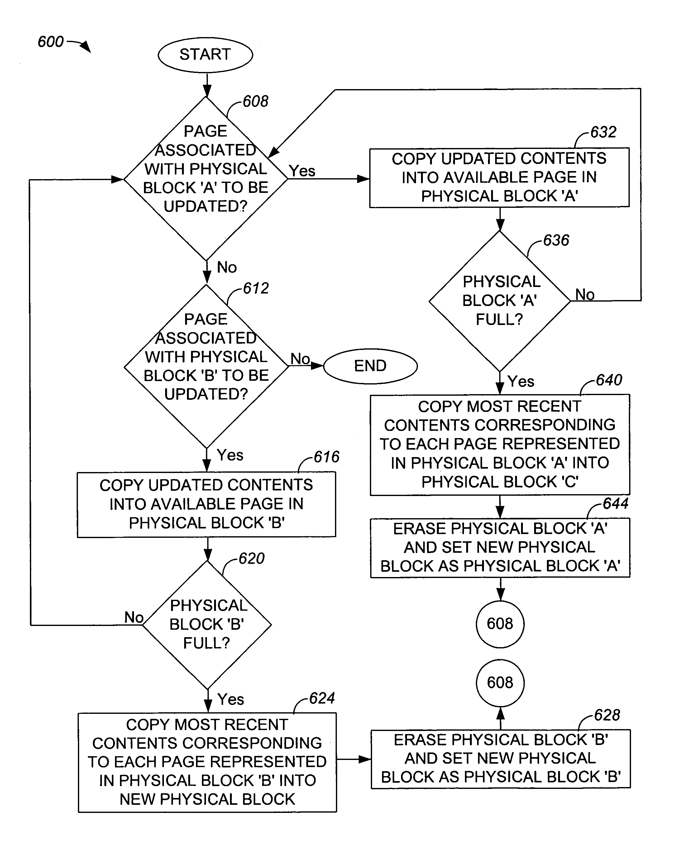
[0032]Reducing the amount of overhead that is needed to store or otherwise rewrite updated pages when single pages are updated may enable an overall system, e.g., an overall host system with an embedded non-volatile memory chip, would enable the overall system to operate more efficiently. Copying an entire physical block, e.g., a block associated with a file allocation table (FAT), each time a single page associated with the physical block is to be updated may use a significant amount of overhead and, as a result, may be relatively inefficient.

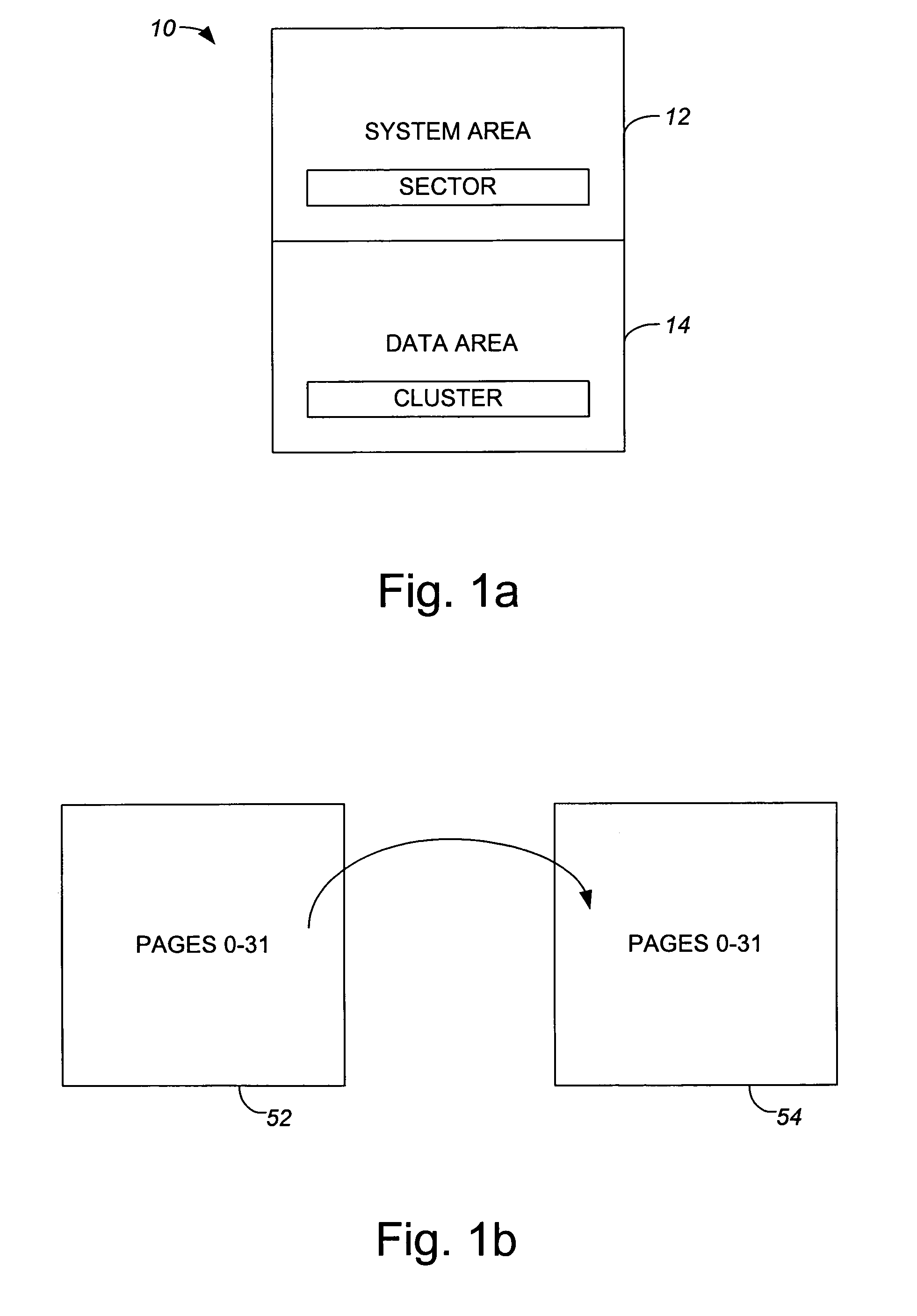
[0033]By splitting a logical block such as a logical FAT block into a plurality of physical blocks, e.g., two physical blocks, when an overall flash memory system is formatted, each of the physical blocks associated with the logical block is substantially only partially full. In other words, a portion of the logical block data may be written into each of a plurality of physical blocks. By way of example, pages 0–15 of a split thirty-two page l...


PUM


Abstract

Methods and apparatus for splitting a single logical block into two or more physical blocks are disclosed. According to one aspect of the present invention, a method for associating a plurality of physical blocks of a non-volatile memory with a logical block that includes of logical block elements involves grouping the logical block elements into at least a first logical set and a second logical set. Data associated with the first logical set is provided to a first physical block, and data associated with the second logical set is provided to a second physical block.

Description

CROSS REFERENCE TO RELATED APPLICATIONS[0001]The present invention is related to co-pending U.S. patent application Ser. No. 10 / 281,739 entitled “WEAR-LEVELING IN NON-VOLATILE SYSTEMS”, filed Oct. 28, 2002; co-pending U.S. patent application No. 10 / 281,670 entitled “TRACKING THE MOST FREQUENTLY ERASED BLOCKS IN NON-VOLATILE MEMORY SYSTEMS,” filed Oct. 28, 2002; co-pending U.S. patent application Ser. No. 10 / 281,824 entitled “TRACKING THE LEAST FREQUENTLY ERASED BLOCKS IN NON-VOLATILE MEMORY SYSTEMS”, filed Oct. 28, 2002; co-pending U.S. patent application Ser. No. 10 / 281,855 entitled “METHOD AND APPARATUS FOR GROUPING PAGES WITHIN A BLOCK”, filed Oct. 28, 2002; co-pending U.S. patent application Ser. No. 10 / 281,762 entitled “METHOD AND APPARATUS FOR RESOLVING PHYSICAL BLOCKS ASSOCIATED WITH A COMMON LOGICAL BLOCK,” filed Oct. 28, 2002; which are each incorporated herein by reference in their entireties.BACKGROUND OF THE INVENTION[0002]1. Field of Invention[0003]The present invention...

Claims


Application Information

Patent Timeline
Patent Type & Authority Patents(United States)
IPC IPC(8): G11C16/00G06F12/02
CPCG06F12/0246G06F2212/7202G06F12/02
Inventor CHANG, ROBERT C.QAWAMI, BAHMANSABET-SHARGHI, FARSHID
Owner SANDISK TECH LLC
Why Eureka
Try Eureka