Method of generating a 3-dimensional effect

a 3-dimensional effect and generating technology, applied in the field of generating a 3-dimensional effect, can solve the problems of methods described in the prior ar

Inactive Publication Date: 2006-05-09
MERCK PATENT GMBH
View PDF7 Cites 9 Cited by
  • Summary
  • Abstract
  • Description
  • Claims
  • Application Information

AI Technical Summary

Benefits of technology

[0014]Furthermore, the inventors have found that complicated images of CLC flakes are not required to provide a perception of depth in an image. By utilising both enantiomeric forms of CLC materials in a printed / coated design an impression of depth is obtained, even when the two enantiomeric forms are printed into different regions or form different images, when viewed through a viewing device comprising two circular polarisers, provided that the handedness of each polariser is different and that each eye can only see the image through one of the polarisers. The circular polarisers necessary for this viewing device need not be manufactured from similar liquid crystalline materials but standard circular polarisers may be used.
[0015]This effect can be seen from a distance of several meters (for example, up to at least 1 meter, preferably up to at least 2 meters, especially to at least 5 meters) and, when combined with other properties of CLC materials such as angular colour dependency and thermochromism, imparts an additional security feature. An advantage of this kind of device as a security feature is that the effect is destroyed if the feature is covered with material such as adhesive tape or clear polymer films since it disturbs the polarisation state of the light.
[0027]By utilising this method, a 3-dimensional effect can easily be obtained without the use of flaked LC pigment materials or complicated manufacturing or assembling techniques. The images can be provided by two-stage printing or coating and UV curing of a reactive chiral LC materials to form the two different perspective images required for 3-D imaging. The image can be viewed with standard circular polariser devices, provided that each eye sees the image through only one of the circular polarisers.
[0039]A second preferred embodment of the present invention relates to a method of generating a 3-dimensional effect by providing at least one first and at least one second image layer of a chiral liquid crystal material, wherein one of said first and second image layers reflects right-handed circularly polarised light and the other reflects left-handed circularly polarised light, characterized in that the first and second images are not directly superimposed onto each other and / or do not form a stereo pair of identical images.
[0042]This effect can be seen from a distance of several meters (for example, up to at least 1 meter, preferably upto at least 2 meters, especially to at least 5 meters) and when combined with other properties of CLC materials such as angular colour dependency and thermochromism imparts an additional security feature. An advantage of this kind of device as a security feature is that the effect is destroyed if the feature is covered with material such as adhesive tape or clear polymer films since it disturbs the polarisation state of the light.

Problems solved by technology

However, the methods described in prior art have several drawbacks.

Method used


Image

  • Method of generating a 3-dimensional effect
  • Method of generating a 3-dimensional effect
  • Method of generating a 3-dimensional effect

Examples


example 1

3-D Imaging Process Utilising Polymerised Liquid Crystal Material

[0090]A polymerisable liquid crystal mixture was prepared as follows:

[0091]

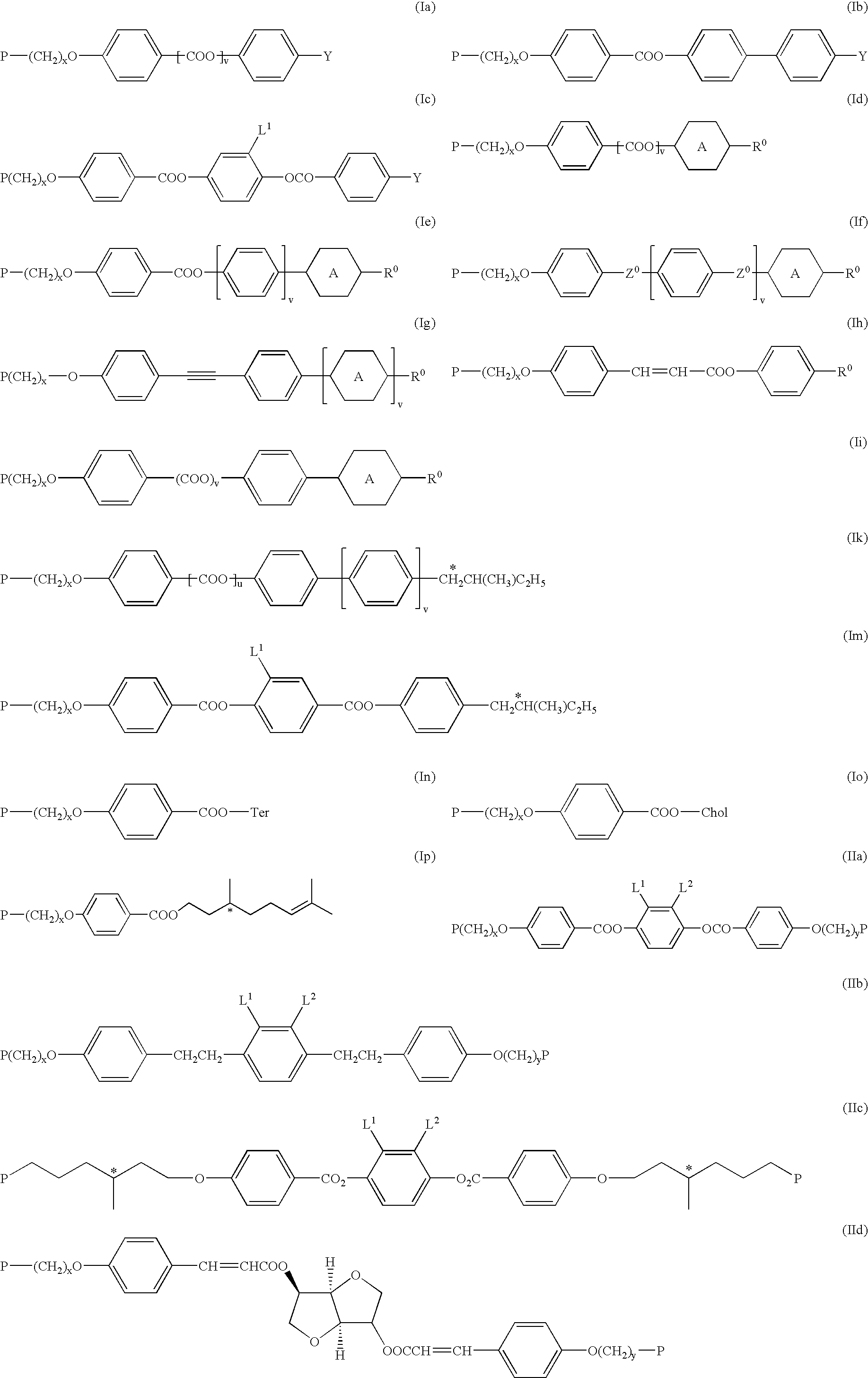
Compound (A)10.24%Compound (B)8.18%Compound (C)1.58%Compound (D)9.92%Irgacure 3692.62%Fluorad FC 1710.12%Xylene67.34%(A)(B)(C)(D)

[0092]Compounds (A), (B) and (C) can be prepared according to or in analogy to the methods described in D. J. Broer et al., Makromol. Chem. 190, 3201–3215 (1989). Compound (D) and its preparation are described in GB 2,280,445. Irgacure 369 is a commercially available photoinitiator (Ciba Geigy). Fluorad FC 171 is a commercially available surfactant (3M Inc.).

[0093]This mixture was split into two equal parts and the chiral compound (E1) and (E2), respectively, was added in an amount of 5% by weight of the total amount of solid components, to impart the required reflected colour properties. This yielded Mixture 1 and 2 as described below:

[0094]

Mixture 1: Host + Compound (E1) (5% by weight of total solids)Mixture 2: Host ...

example 2

Perceived Depth Process

[0101]A nematic liquid crystal host mixture is prepared as below.

[0102]

Material%8.01%3.43%14.85%14.86%11.44%29.13%13.72%2.28%2.28%

[0103]Chiral dopants are added to this host to prepare two mixtures that have the same reflection colour and differ only in their chirality.

[0104]

HOST87.09%HOST87.09%S8112.77%R8112.77%S20115.23%R20115.23%E14.91%E24.91%R / S-811 and R / S-2011 are commercially available chiral dopants (from Merck KGaA, Darmstadt, Germany).

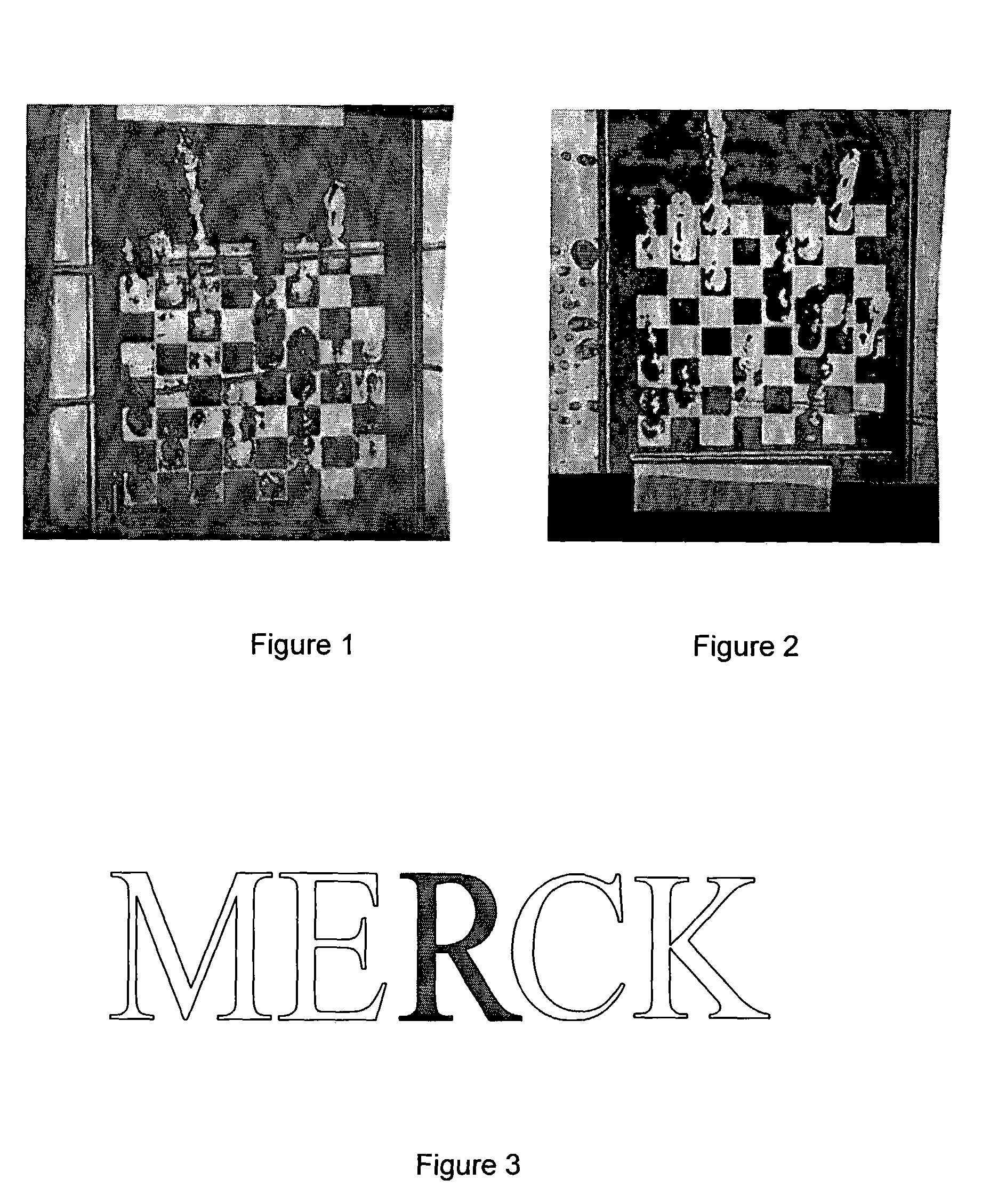
[0105]These mixtures are then encapsulated and the capsules formed into an ink system. The inks are printed by screen printing techniques to produce the design as schematically depicted in FIG. 3, wherein the “R” is printed in the opposite chirality from the other letters.

[0106]When viewed through a viewing device comprising a left handed and a right handed circular polariser, such that each eye only sees the image through one polariser a perceived depth is seen in the image. The “R” seems to have be at another distance...


PUM

PropertyMeasurementUnit
temperatureaaaaaaaaaa
temperaturesaaaaaaaaaa
distanceaaaaaaaaaa

Abstract

A method for generating a 3-dimensional effect involves providing at least one first image layer of a chiral liquid crystal material, and at least one second image layer of a chiral liquid crystal material, wherein one of the first and second image layers reflects right-handed circularly polarised light and the other reflects left-handed circularly polarised light, is suitable creating a 3-dimensional image that can be used for decorative and security applications.

Description

FIELD OF THE INVENTION[0001]The invention relates to a method for generating a 3-dimensional effect, to a 3-dimensional image produced by said method, their use for decorative and security applications and to security markings and documents of value comprising such a 3-dimensional image.BACKGROUND AND PRIOR ART[0002]The generation of 3-dimensional effects based upon the projection of two different perspective images being viewed in the left and right eyes is known in prior art. Typically two images of the same object are prepared with a small change in the visual perspective of the image. These images are then viewed in such a manner that each eye of the observer only sees one of the images. The visual process then interprets the two separate images as a single 3-dimensional image. This can be achieved in a variety of manners.[0003]Steroscopic viewers require the use of two distinct images which are viewed through two distinct optical paths.[0004]Composite images can be prepared by ...

Claims


Application Information

Patent Timeline
Patent Type & Authority Patents(United States)
IPC IPC(8): C09K19/52G02B5/30G02B27/22
CPCG02B5/3016G02B27/22B42D2033/26Y10T428/10Y10T428/24802B42D25/364B42D25/391C09K2323/00
Inventor KUNTZ, MATTHIASRIDDLE, RODNEYPATRICK, JOHNHAMMOND-SMITH, ROBERT
Owner MERCK PATENT GMBH
Why Eureka
Try Eureka