
Manipulator for microscopy sample preparation and methods for making and use thereof

Active Publication Date: 2006-05-09
WESTERN DIGITAL TECH INC
View PDF4 Cites 203 Cited by
  • Summary
  • Abstract
  • Description
  • Claims
  • Application Information

AI Technical Summary

Benefits of technology

[0017]A method of forming a probe for a manipulator for handling micron-scale samples comprises necking a capillary tube including a bore to form a closed and pointed end thereof, removing the closed end of the capillary tube, and coating the capillary tube with a conductive coating. The step of removing the closed end of the capillary tube provides the capillary tube with a distal end having a truncated conical shape with a generally flat face, the face having a diameter along a minor axis of less than about 50 μm, the bore of the capillary tube being exposed at the flat fac

Problems solved by technology

Such sample preparation is typically destructive to the device being inspected.
The burden of sample preparation has kept TEM from being more widely accepted for routine inspections.
A disadvantage of the in-situ technique is that the membrane 210 must be cut from the probe by further milling.
Besides possibly disturbing the feature of interest through the welding, cutting, and cleaning processes, the in-situ method also ties up the FIB system, reducing throughput.
Unfortunately, in other instances the membrane 210 flies away from the probe.
However, because the membrane 210 is held to the probe only by electrostatic forces, it is often difficult to position the membrane 210 precisely on the TEM support grid.
While the ex-situ method is desirable over the in-situ method because it frees the FIB system for other work, and does not include the steps of welding the membrane 210 to the probe, cutting the membrane 210 from the probe, and cleaning excess platinum from the membrane 210, the ex-situ method suffers from low yield due to the unpredictability of the electrostatic forces on which it relies.

Method used


Image

  • Manipulator for microscopy sample preparation and methods for making and use thereof
  • Manipulator for microscopy sample preparation and methods for making and use thereof
  • Manipulator for microscopy sample preparation and methods for making and use thereof

Examples


Embodiment Construction

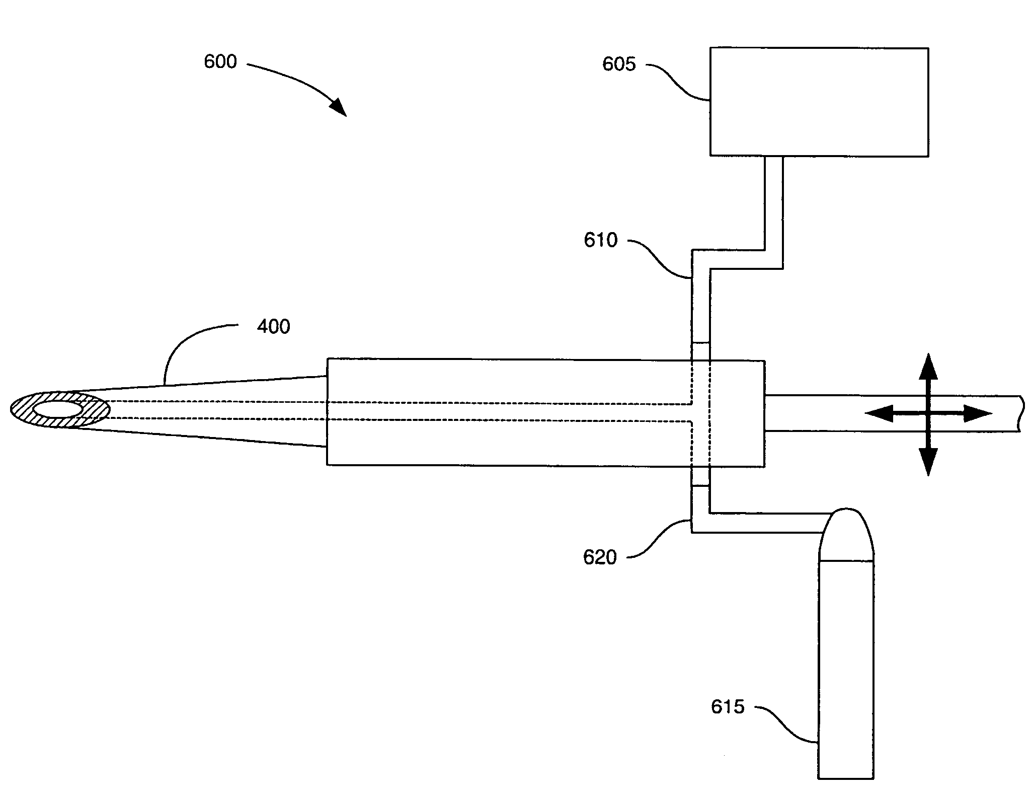
[0036]The present invention provides improvements for both in-situ and ex-situ preparation of micron-scale samples. A manipulator for handling micron-scale samples, according to an embodiment of the invention, comprises a probe including a bore and an electrically conductive surface. The electrically conductive surface dissipates static charges that might otherwise interact with the sample as the probe is brought into proximity to the sample. A vacuum drawn through the bore pulls the sample to the probe and secures the sample to the probe during subsequent handling. The disclosure also describes manipulator systems that include the manipulator, methods for microscopy inspection that employ at least the probe of the manipulator, and methods for making the probe.

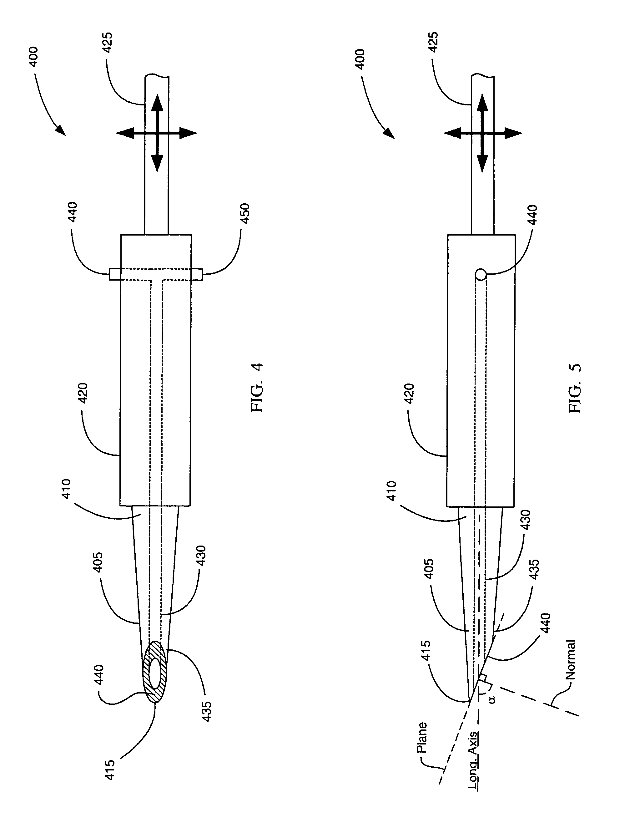
[0037]FIGS. 4 and 5 show bottom and side views, respectively, of a manipulator 400 for handling micron-scale samples according to an embodiment of the present invention. Micron-scale samples can include micron-scale devices an...


PUM


Abstract

Manipulators for handling micron-scale samples, methods for making probes for the manipulators, and methods for using the manipulators are provided. An exemplary manipulator includes a probe, a probe holder, and a mechanical positioner. The probe includes an electrically conductive surface, a proximal end and a distal end where the distal end has a truncated conical shape with a generally flat face, and a bore extending from the proximal end to the face. The probe holder engages the proximal end and includes an inlet in fluid communication with the bore and with a source of sub-ambient pressure. An exemplary microscopy inspection method includes forming a free-standing membrane, positioning the probe of the manipulator proximate to the membrane, drawing the membrane to the face by drawing a vacuum through the bore, placing the membrane on a sample support, and inspecting the membrane with a microscope.

Description

BACKGROUND OF THE INVENTION[0001]1. Field of the Invention[0002]The disclosure relates generally to the field of device inspection by electron microscopy, and more particularly to handling samples made for such inspection.[0003]2. Description of the Prior Art[0004]Various devices, such as semiconductor products and disk drive transducers, comprise features that are fabricated at micron and smaller scales. For quality assurance and trouble-shooting purposes, it is often necessary to inspect certain features of such devices at different stages in the manufacturing process. Electron microscopy is a common tool for such inspections. Scanning electron microscopy (SEM) creates images by scanning an electron beam across a surface and measuring the electrons that are reflected towards an electron detector from features on the surface. Another technique, transmission electron microscopy (TEM), creates images by shining an electron beam on a very thin film and detecting those electrons that p...

Claims


Application Information

Patent Timeline
IPC IPC(8): G21K5/10
CPCG01N1/32H01J37/20G01N2035/00059H01J2237/31745G01N2203/0417
Inventor WANG, HAIFENGVINH, LOC
Owner WESTERN DIGITAL TECH INC
Features
  • Generate Ideas
  • Intellectual Property
  • Life Sciences
  • Materials
  • Tech Scout
  • Unparalleled Data Quality
  • Higher Quality Content
  • 60% Fewer Hallucinations
Learn More