
Internal combustion engine control device

a control device and internal combustion engine technology, applied in the direction of electric control, brake systems, instruments, etc., can solve the problems of insufficiently ensuring stable engine operation, inability to provide satisfactory torque compensation, etc., to achieve satisfactory torque compensation and stable operation performance

Inactive Publication Date: 2006-05-09
NISSAN MOTOR CO LTD
View PDF7 Cites 4 Cited by
  • Summary
  • Abstract
  • Description
  • Claims
  • Application Information

AI Technical Summary

Benefits of technology

The present invention provides an internal combustion engine control device that can compensate for torque decline and ensure stable operating performance even when fuel property changes. The device includes an intake air quantity control section, a fuel injection quantity control section, a combustion mode control section, an intake air quantity correcting section, and a torque correction value modifying section. The intake air quantity control section controls the amount of air drawn into the engine, the fuel injection quantity control section controls the amount of fuel injected into the engine, the combustion mode control section selects the combustion mode of the engine, and the intake air quantity correcting section uses a torque correction value to compensate for torque decline resulting from the selected combustion mode. The torque correction value modifying section modifies the torque correction value based on changes in fuel property.

Problems solved by technology

Thus, the internal combustion engine control device described in the above mentioned reference cannot provide a satisfactory torque compensation and cannot sufficiently ensure stable operating performance of the engine when the fuel property has changed.

Method used


Image

  • Internal combustion engine control device
  • Internal combustion engine control device
  • Internal combustion engine control device

Examples


Embodiment Construction

[0062]Selected embodiments of the present invention will now be explained with reference to the drawings. It will be apparent to those skilled in the art from this disclosure that the following description of the embodiment of the present invention is provided for illustration only and not for the purpose of limiting the invention as defined by the appended claims and their equivalents.

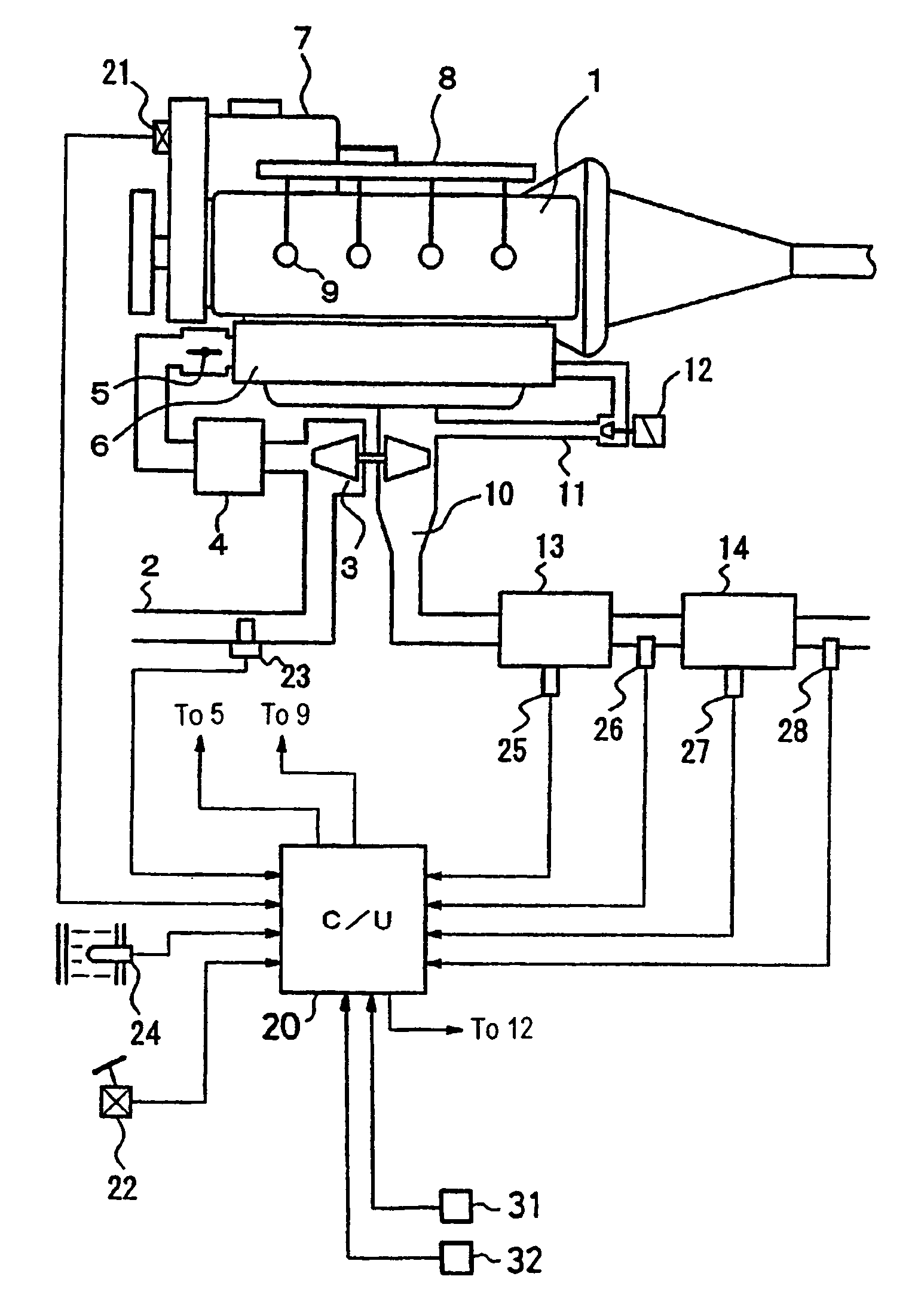
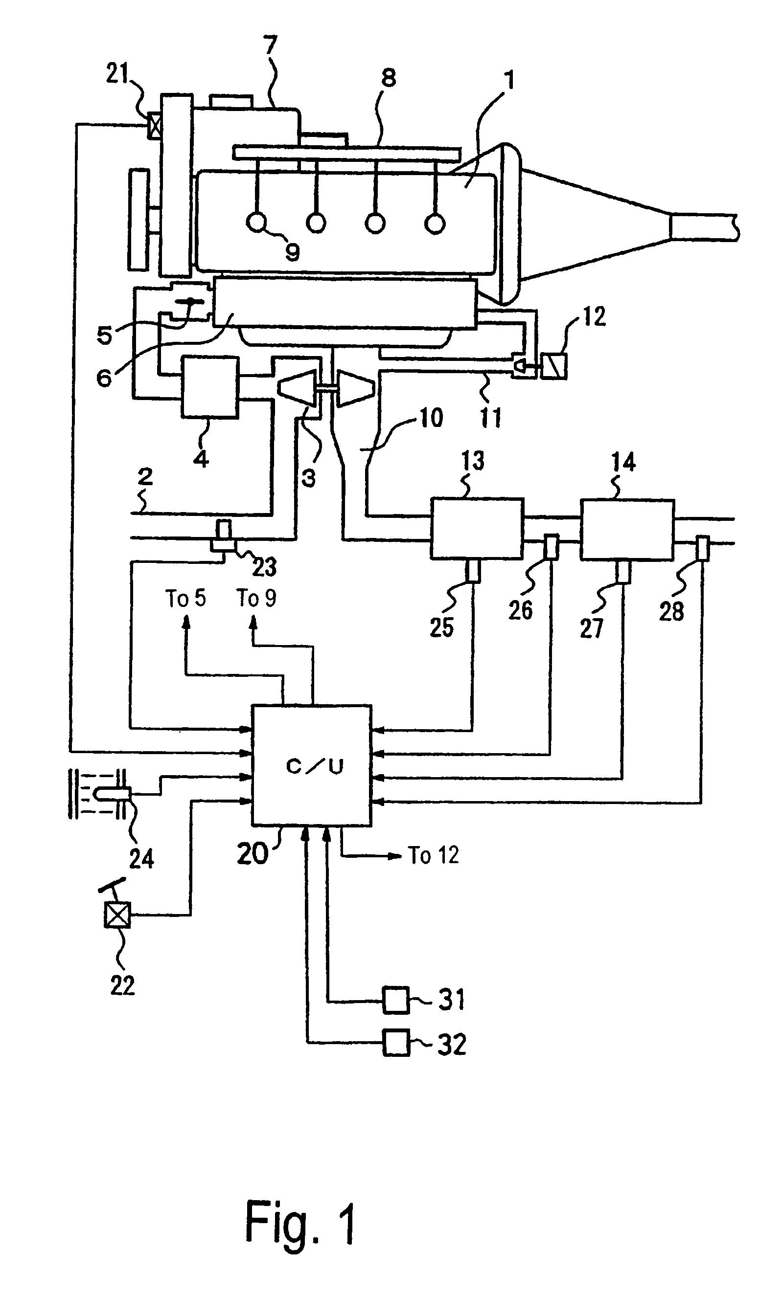
[0063]Referring initially to FIG. 1, an internal combustion engine control device is illustrated in accordance with a preferred embodiment of the present invention. In this embodiment, the internal combustion engine control device is adapted to be used in a diesel engine 1 as seen in FIG. 1. The diesel engine 1 is provided with an intake air compressor of a variable nozzle turbocharger 3 installed in an intake passage 2 of the diesel engine 1. The intake air is supercharged by the intake air compressor, cooled by an intercooler 4, passes through an intake throttle valve 5, and passes through a collect...


PUM


Abstract

An internal combustion engine control device is configured to take a fuel property into account when compensating for torque decline that occurs when a prescribed combustion control mode is executed. The internal combustion engine control device is configured to calculate a first modification coefficient designed to modify a first torque correction coefficient corresponding to a air-fuel ratio based on the specific gravity of the fuel, a second modification coefficient designed to modify a second torque correction coefficient corresponding to a working gas quantity based on the specific gravity of the fuel, and a third modification coefficient designed to modify a third torque correction coefficient corresponding to a fuel injection timing based on an aromatic component content ratio of the fuel. The internal combustion engine control device is then configured to multiply the first, second and third modification coefficients together to calculate a modification coefficient for modifying a torque correction value.

Description

CROSS-REFERENCE TO RELATED APPLICATIONS[0001]This application claims priority to Japanese Patent Application No. 2004-054516. The entire disclosure of Japanese Patent Application No. 2004-054516 is hereby incorporated herein by reference.BACKGROUND OF THE INVENTION[0002]1. Field of the Invention[0003]The present invention relates to an internal combustion engine control device. More specifically, the present invention relates to an internal combustion engine control device that provides a stable operating performance of an engine even when a fuel property changes.[0004]2. Background Information[0005]Japanese Laid-Open Patent Publication No. 2000-320386 discloses an internal combustion engine control device adapted to a diesel engine. In the internal combustion engine control device disclosed in this reference, when the engine is being controlled in a prescribed combustion control mode to increase a temperature of a catalytic converter, a basic fuel injection quantity, which is match...

Claims


Application Information

Patent Timeline
Patent Type & Authority Patents(United States)
IPC IPC(8): B60T7/12F02B3/00F02D43/00F02B17/00F02D41/00F02D41/02F02D41/04F02D41/38F02D45/00
CPCF02D41/0002F02D41/024F02D41/402F02D19/061F02D19/0649F02D19/088F02D41/0025Y02T10/36F02D41/028F02D41/403F02D2200/0611F02D2250/18Y02T10/44Y02T10/26Y02T10/42Y02T10/12Y02T10/30Y02T10/40
Inventor MIURA, MANABU
Owner NISSAN MOTOR CO LTD
Learn More