High-resolution in-plane tuning fork gyroscope and methods of fabrication

a gyroscope and tuning fork technology, applied in the field of high-resolution inplane fork gyroscopes, can solve the problems of conventional mems vibratory gyroscopes that have yet to achieve inertial grade performance, and achieve performance levels comparable to optical and macro-mechanical counterparts

Active Publication Date: 2006-05-16
GEORGIA TECH RES CORP
View PDF14 Cites 80 Cited by
  • Summary
  • Abstract
  • Description
  • Claims
  • Application Information

AI Technical Summary

Problems solved by technology

However, they are yet to achieve performance levels comparable to their optical and macro-mechanical counterparts in high-precision applications such as space and tactical / inertial navigation systems.
Conventional MEMS vibratory gyroscopes have yet to achieve inertial grade performance.

Method used


Image

  • High-resolution in-plane tuning fork gyroscope and methods of fabrication
  • High-resolution in-plane tuning fork gyroscope and methods of fabrication
  • High-resolution in-plane tuning fork gyroscope and methods of fabrication

Examples


Embodiment Construction

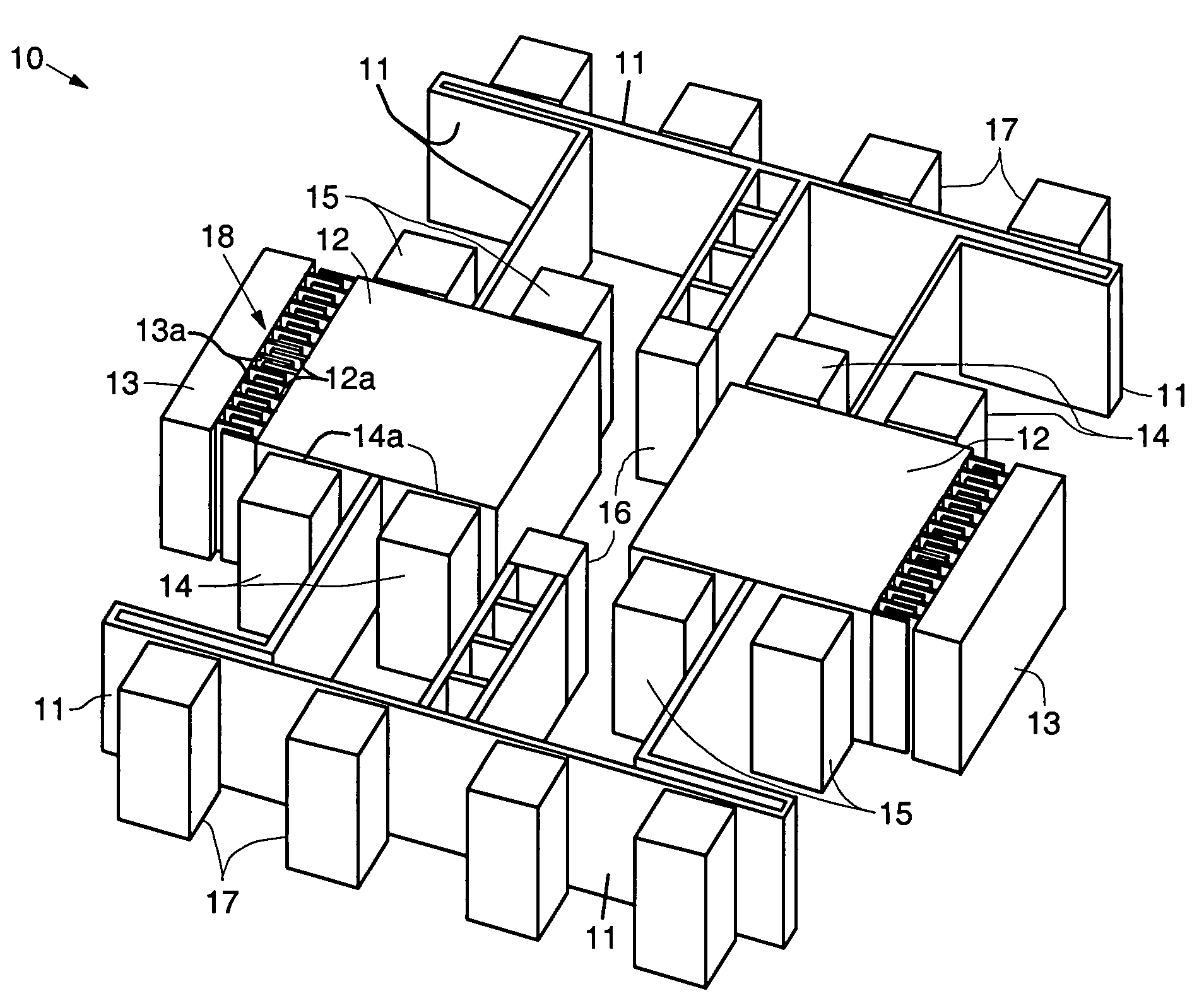
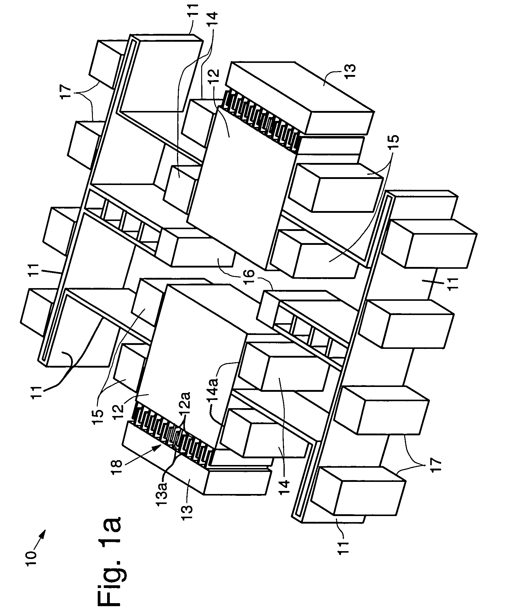
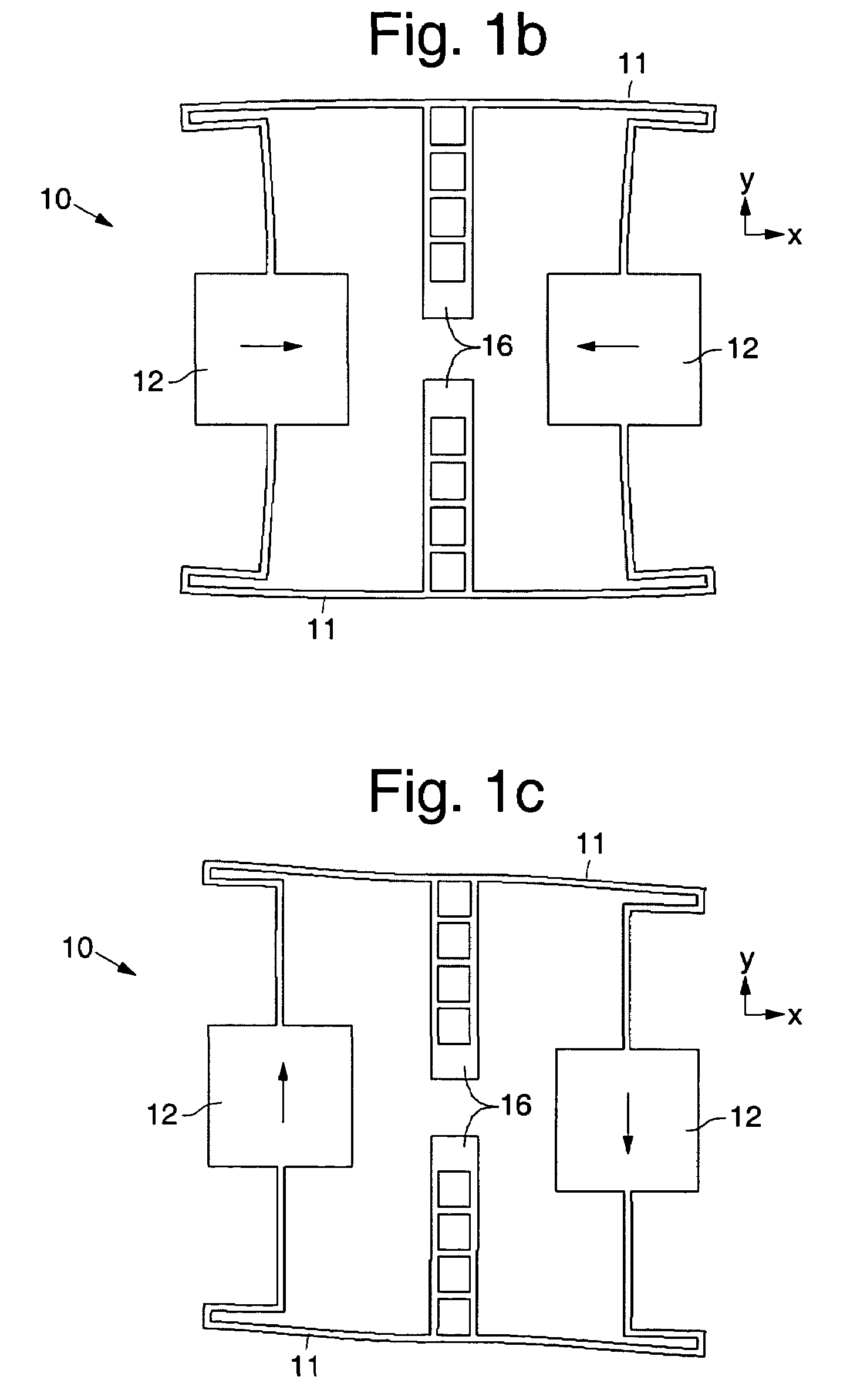
[0030]Referring to the drawing figures, FIG. 1a illustrates components of an exemplary in-plane solid-mass single-crystal silicon tuning fork gyroscope 10 in accordance with the principles of the present invention. FIG. 1 shows only a top or device layer 23 (FIGS. 3a–3d) With reference to FIGS. 3a–3d, the gyroscope 10 comprises a lower or handle layer 21 or substrate 21 and the top or device layer 23, with an insulating layer 22 disposed there between. During fabrication, portions of the lower and upper layers 21, 23 and insulating layer 22 are removed using microelectronic fabrication processes to form the gyroscope 10.

[0031]It is to be understood, that while the exemplary gyroscope 10 described herein was fabricated using silicon, other semiconductor materials, such as quartz or polycrystalline silicon, for example, or an electrically-conductive substrate, for example, may readily be employed. Thus, it is to be understood that the present invention is not limited to silicon struct...


PUM

PropertyMeasurementUnit
massaaaaaaaaaa
displacement amplitudesaaaaaaaaaa
frequencyaaaaaaaaaa

Abstract

A microstructure comprising an in-plane solid-mass electrically conductive tuning fork gyroscope and fabrication methods. The gyroscope is formed using substrate material having lower and upper layers sandwiching a sacrificial insulating layer. An exemplary gyroscope comprises a low-resistivity single-crystal silicon substrate having a lower support layer and an upper flexible support layer. Two opposed proof masses that are separated from the lower support layer lie in and are supported by the upper flexible support layer. Two drive electrodes are disposed adjacent to the proof masses and are insulatably supported by the lower support layer and are separated from the upper flexible support layer. Sense, balance and tuning electrodes are disposed adjacent to the proof masses and are insulatably supported by the lower support layer and are separated from the upper flexible support layer. The operational mode shapes are in-plane with the substrate surface and only measures angular motion that are orthogonal to the plane of the substrate. The microstructure flexural design enables the sense and the drive resonant frequencies to occur in close proximity of one another. This enables matched-mode operation of the device thereby ensuring maximum sensitivity.

Description

[0001]This application claims the benefit of U.S. Provisional Application No. 60 / 536,333, filed Jan. 13, 2004.GOVERNMENT RIGHTS[0002]The present invention was funded by the National Science Foundation under contract No. ECS-0301900. The U.S. Government has certain rights in this invention.BACKGROUND[0003]The present invention relates generally to semiconductor microstructures, such as Micro-Electro-Mechanical Systems (MEMS) devices, along with fabrication and operational methods, and more particularly, to a high resolution in-plane fork gyroscope, and methods of manufacture and operation, which is preferably formed using a silicon-on-insulator (SOI) substrate.[0004]Vibratory micromachined gyroscopes rely on Coriolis-induced transfer of energy between two vibration modes to sense rotation. Micromachined gyroscopes are increasingly employed in consumer and automotive applications, primarily due to their small size and low power requirements. However, they are yet to achieve performanc...

Claims


Application Information

Patent Timeline
Patent Type & Authority Patents(United States)
IPC IPC(8): G01P9/04G01C19/56G01P1/04H01L21/461
CPCG01C19/5719Y10T29/49002
Inventor AYAZI, FARROKHZAMAN, MOHAMMAD FAISAL
Owner GEORGIA TECH RES CORP
Why Eureka
Try Eureka