
Run-flat insert for tires

a technology for inserts and tires, applied in inflatable tires, vehicle components, transportation and packaging, etc., can solve problems such as limiting the usefulness of inserts, and achieve the effects of improving the performance of inserts, stable alignment, and high resistance to rotation

Inactive Publication Date: 2006-05-16
MICHELIN RECH & TECH SA
View PDF4 Cites 18 Cited by
  • Summary
  • Abstract
  • Description
  • Claims
  • Application Information

AI Technical Summary

Benefits of technology

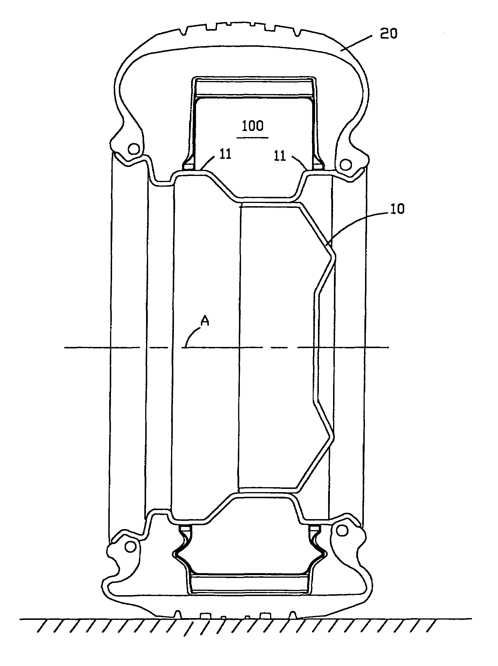
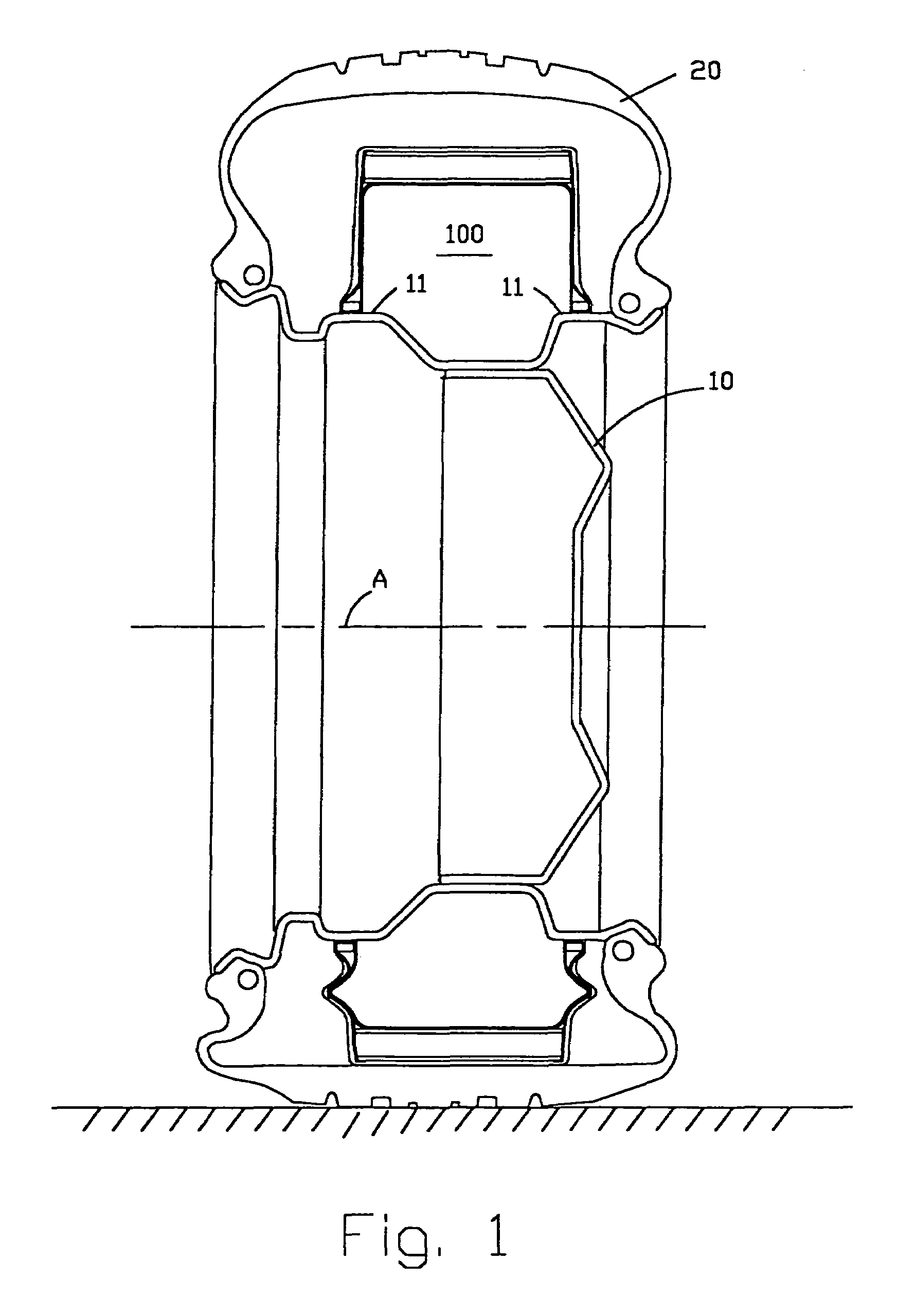
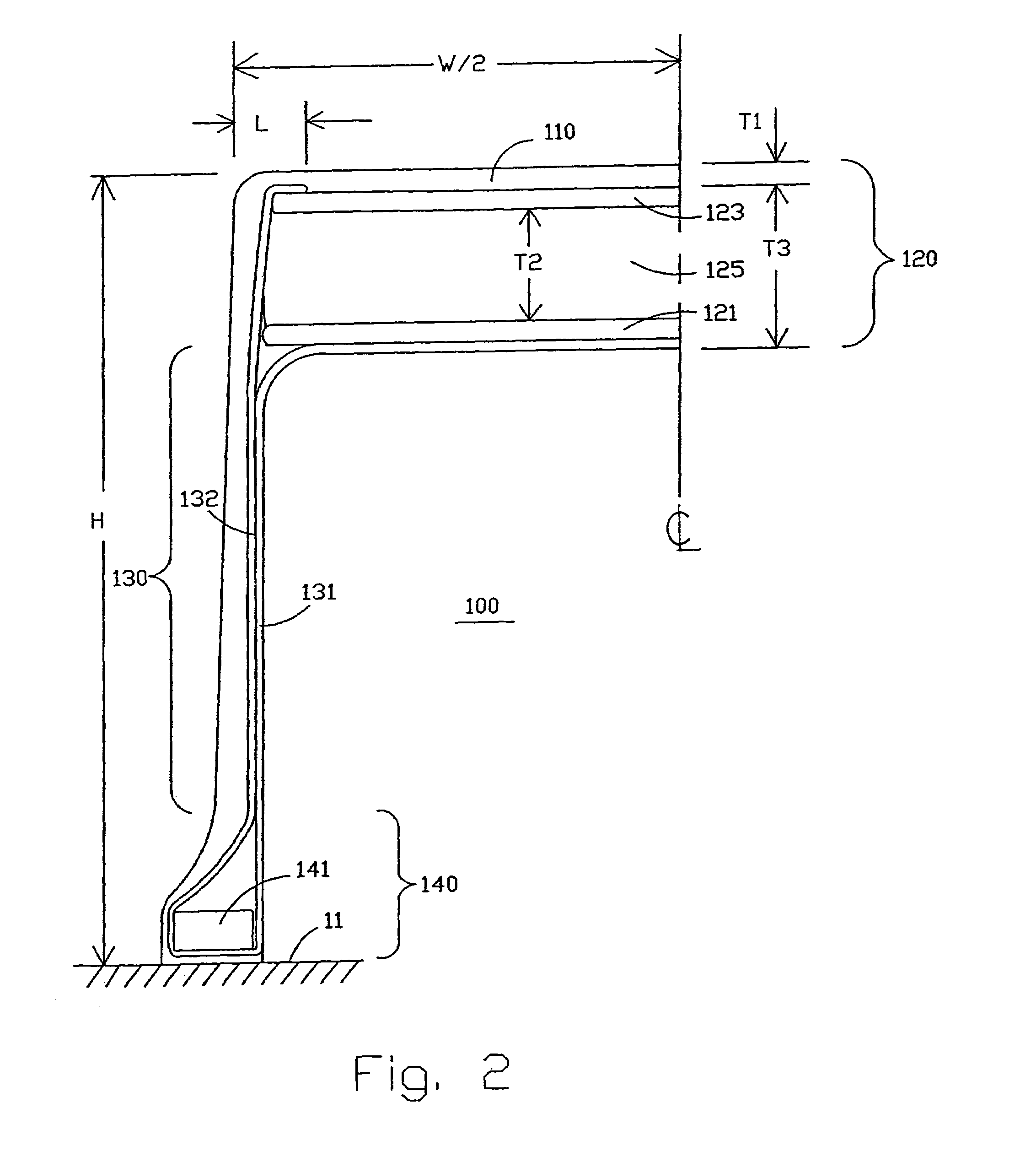
[0010]Run-flat inserts may be tightly fixed to the wheel rim or require the use of extra material or spacers to maintain proper lateral location of the insert on the rim. In the instant invention, the base member has a high resistance to rotation about a longitudinal axis. The base member may have monolithic cores comprising a generally rectangular cross-section having a width of about 5% of the section width of the insert, and the core has a height equal to about 50 percent of its width. Alternatively, the core may comprise one of several arrangements of reinforcing wires. When this base member structure is coupled with radially oriented sidewall portions, the insert has the advantage of maintaining a stable alignment on the rim and requires no additional internal spacers or reinforcements.
[0011]Performance of the insert improves when the sidewall portion is biased to buckle advantageously in an axially outward direction when subjected to compressive loading. In the instant invention the sidewall is biased by an elastomeric wedge positioned in the sidewall essentially mid way between the first membrane and the base member. The wedge forces a curvature in the profile of the carcass layer. When the wedge is combined with the proper thickness of rubber on the outside of the carcass layer, the invention obtains the desired result of a consistent outward buckling of the sidewall in the region contacting the tire.
[0014]The invention permits the designer to adjust the effective contact pressure as a design parameter of the insert. The contact pressure is approximated by the product of the shear modulus of elasticity of the shear layer, times the radial thickness of the annular band, and divided by the radius of the outermost extent of the second membrane. This contact pressure will normally be in the range of about 2 bar to about 6 bar. A contact pressure of about 3 bar yields a good compromise between the size and mass of the insert and vehicle performance.

Problems solved by technology

This solution has limited capability to absorb sharp load inputs from the road, thereby operationally limiting the usefulness of the insert.

Method used


Image

  • Run-flat insert for tires
  • Run-flat insert for tires
  • Run-flat insert for tires

Examples


Embodiment Construction

[0026]The invention and its several variations will be better appreciated from the following detailed description. The Figures and detailed description disclose several exemplary illustrations of particular variations of the invention as of the invention. One skilled in the art will recognize that particular elements of these variations may be selected or combined to yield still further examples within the spirit and scope of the invention.

[0027]The following nomenclature and definitions are common to all variations of the invention disclosed herein. Similar reference numbers are used throughout to describe the same element or material. Similar elements are not discussed in detail when disclosed in a subsequent variation of the invention.

[0028]Definitions of terms[0029]“inner” or “inward” means toward the interior of the insert.[0030]“outer” or “outward” mean towards the exterior of the insert.[0031]“axial” refers to a direction that is parallel to the axis of rotation of the insert...


PUM


Abstract

A run-flat insert 200 for enabling a vehicle to run for limited duration on a deflated tire 20, is mounted in an assembly comprising a pneumatic tire 20 and a wheel rim 10, and said insert is mounted inside the tire and secured to the wheel rim. The insert 200 has improved characteristics in load carrying, vehicle handling, mass, and shock transmission. Such a run-flat insert 200 comprises an outer, reinforced annular band 220 that is coupled with a sidewall portion 230 having little resistance to compressive loads, and the sidewall portion 230 tell mates in a base member 240 fitted around the wheel rim 10 for securing the insert 200 to the rim 10.

Description

CROSS-REFERENCE TO RELATED APPLICATIONS[0001]This application is a continuation of International Application No. PCT / US01 / 23163, filed 19 Jul. 2001 and published 30 Jan. 2003 in English as International Publication No. WO 03 / 008209 A1.BACKGROUND OF THE INVENTION[0002]The present invention relates to a run-flat insert for mounting on a wheel rim and inside a pneumatic tire. In case of loss of inflation pressure from the tire, the insert is capable of taking up the vehicle loads. In particular this invention provides improved performance in load carrying, vehicle handling, and mass.[0003]Many solutions have been proposed to provide continued vehicle mobility after loss of inflation pressure in a pneumatic tire. One class of solutions involves fixing a rigid or semi-rigid insert to the wheel rim and inside the tire. Upon loss of inflation pressure, the vehicle is supported by load transmission from the portion of the insert contacting the inside of the tire directly through the insert ...

Claims


Application Information

Patent Timeline
IPC IPC(8): B60C17/04B60C17/06B60C17/01
CPCB60C17/01
Inventor RHYNE, TIMOTHY B.DEMINO, KENNETH W.CRON, STEVEN M.
Owner MICHELIN RECH & TECH SA
Learn More