Cooler for electronic devices

a technology of electronic devices and cooling devices, which is applied in the direction of air heaters, semiconductor/solid-state device details, lighting and heating apparatus, etc., can solve the problems of unfavorable cooling conditions for the central part of the heat sink located underneath the fan, damage and/or a reduction in operating performance, and many electronic components generate significant amounts of heat. , to achieve the effect of reducing the length of the air path through the heat sink channel, increasing the cooling ability of the heat sink, and reducing the temperature differential

Inactive Publication Date: 2006-05-16
ADVANCED ROTARY SYST
View PDF21 Cites 30 Cited by
  • Summary
  • Abstract
  • Description
  • Claims
  • Application Information

AI Technical Summary

Benefits of technology

[0019]It is another object, of the present invention, to provide a cooler for electronic components with increased cooling ability for the heat sink because of the increase in temperature differentials.
[0020]This can be achieved by using a new proposed design. This design provides cool air to the inlet sides of the heat sink by using a radial blower with blades located around air outlets of the heat sink. This blower is driven by a brushless DC electric motor that utilizes a ring type permanent magnet rotor. This rotor has an opening in the center allowing for the transfer of incoming air to the center of the heat sink. The rotors outer circumferential arrayed poles are rigidly secured to the frame of the radial blower. The stator of the motor is rigidly secured to the heat sink and has an opening in its center. The stator is composed of circumferential arrayed coils on the circuit board material. When the current flows through the stator coils the coils acquire a magnetic polarity. The poles of the rotor and stator coils attract and repel depending on the polarities. This action provides for a smooth continuous directional motor rotation.
[0021]Another novelty of the present invention is that the cool air comes simultaneously from opposite sides of the heat sink. Therefore, the heat sink might have a divider located approximately in the middle of the heat sink fins and perpendicular to the axel. The blades of the radial blower are located around the air outlets on the heat sink. Because the ambient air is drawn in from both sides of the heat sink the air path length through the heat sinks channels is effectively halved. This results in an increased cooling ability for the heat sink because of the increase in temperature differentials.

Problems solved by technology

During normal operation many electronic components generate significant amounts of heat.
If this heat is not continuously removed the electronic component may overheat resulting in damage and / or a reduction in operating performance.
However, due to the weak airflow in the area adjacent to fan axle, the conditions for cooling the central part of the heat sink located underneath the fan are unfavorable.
In this case non-uniform cooling of the heat sink and electronic component will take place allowing for bad conditions for the heat exchange process.
However, placement of a centrifugal blower to the side of the heat sink increases the devices size and reduces its effectiveness.
This is because the location of the centrifugal blower leads to insufficient coordination between the direction of channel inlets and direction of airflow supplied from the blower.
The loss in airflow energy results in the reduction of airflow speed in the heat exchanging channels and the reduction of heat exchange efficiency.
Since this centrifugal fan operates by drawing air in through the heat sink, there is an area in the central part of the heat sink that receives poor air circulation.
This results in inefficient cooling of the heat sink's central surface area and uneven cooling of the heat sink in general.
To help overshadow this problem, one has to increase the fans power resulting in an increased airflow but not solving the initial problem.
In addition to the heat dissipation problems, the device is considerably large due to the centrifugal fans placement above the heat sink.
This creates the problem of first extracting the heat from a very small surface area and then transferring this heat, with minimal thermal losses, to the larger heat-dissipating device.
Traditional flat heat sinks are unable to extract and dissipate the required heat from these small component footprints.

Method used


Image

  • Cooler for electronic devices
  • Cooler for electronic devices
  • Cooler for electronic devices

Examples


first embodiment

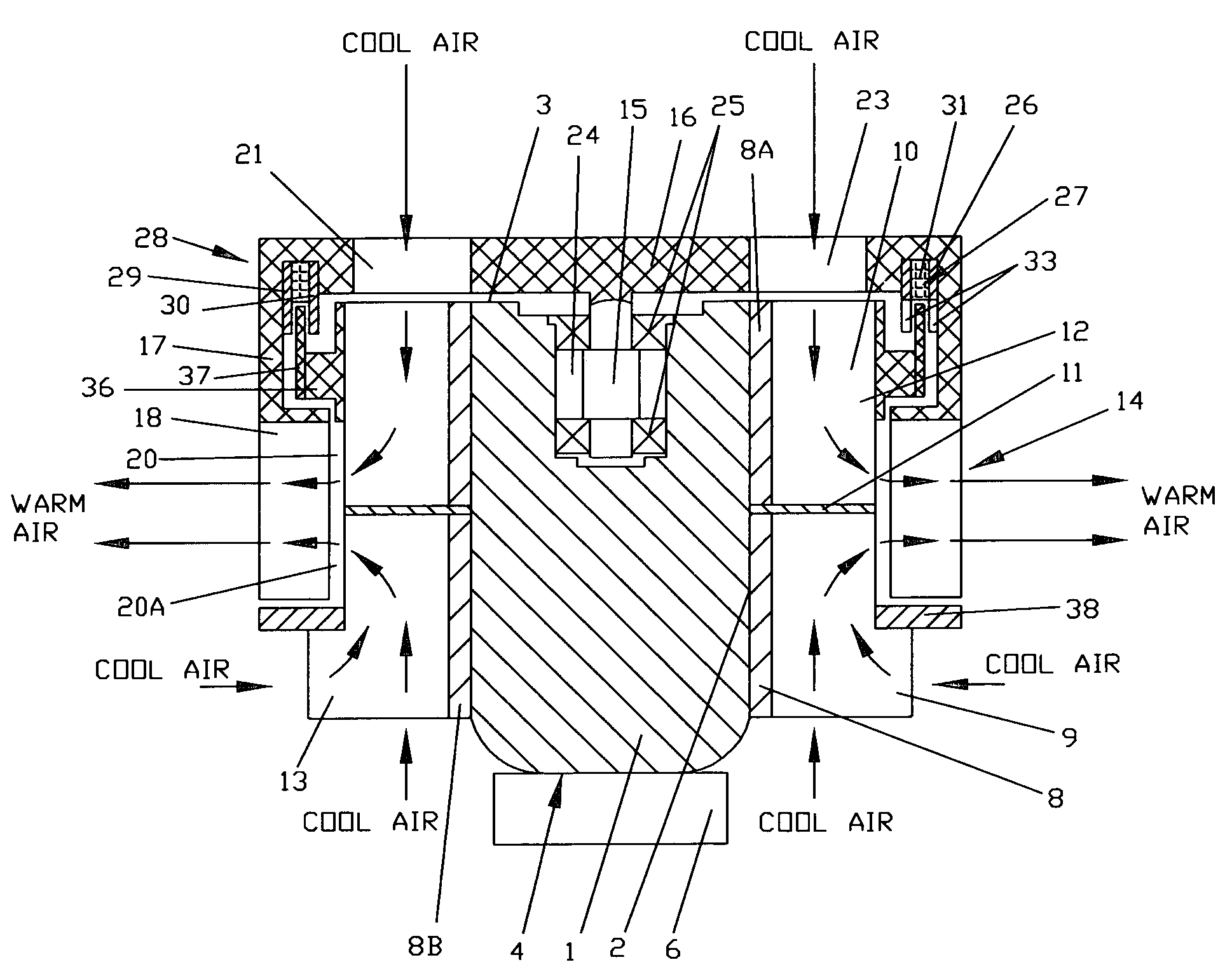
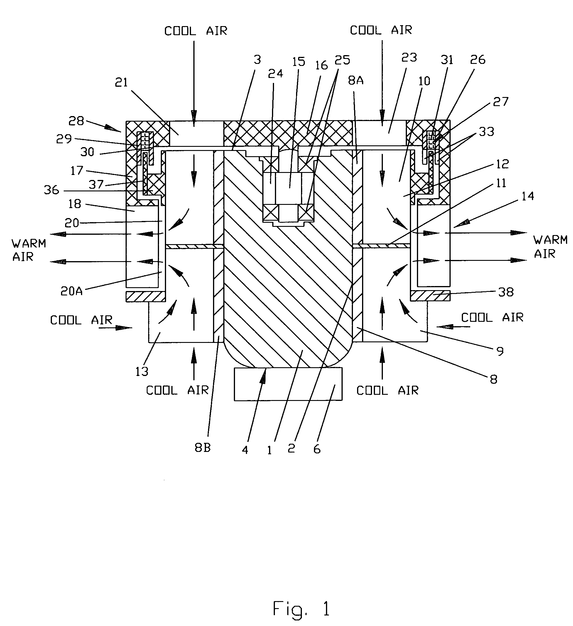
[0036]the present invention is shown in FIG. 1. The cooler includes the central core 1; said central core 1 has a cylindrical shape 2 with a flat top surface 3 and a flat bottom surface 4. The flat bottom surface 4 is for making direct mechanical contact with electronic component heat dissipation footprint 6. Said flat bottom part surface 4 and said electronic component heat dissipation footprint 6 have about the same shape of contact surfaces. Shape the bottom surface usually is the same as the electronic component heat dissipation footprint one.

[0037]The central core 1 is constructed from a good thermal conductive metal and placed inside of a cylindrical bushing 8 that has radial heat exchanging fins 9 protruding out in a radial fashion. Said radial heat exchanging fins 9 protruding out of said central core 1 in radial direction so that surface of said fins 9 is parallel to central axis. The fins 9 may be made spiral-like and bent in the direction of centrifugal type impeller rota...
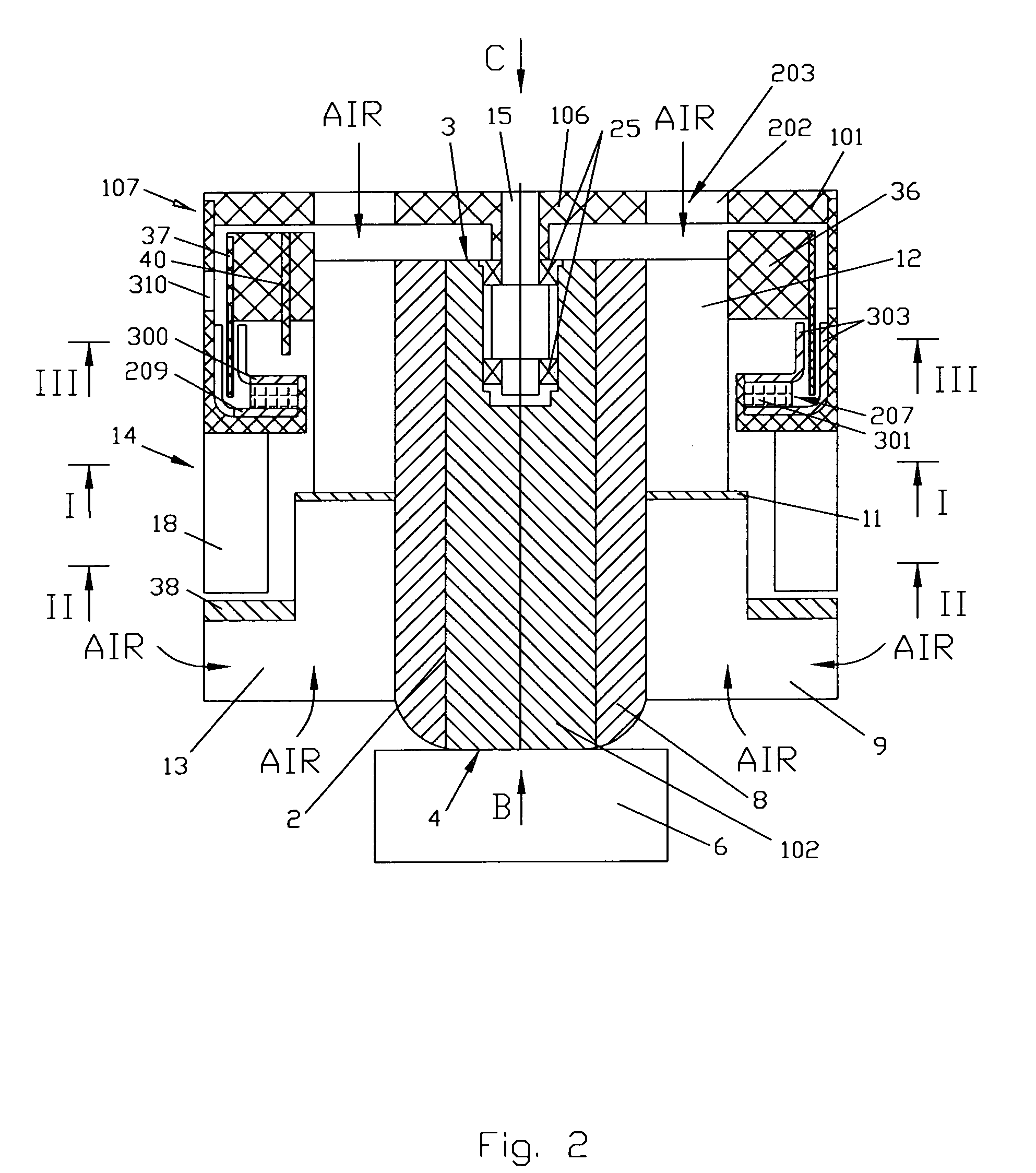
second embodiment

[0043]Around an upper part of the fins 9 is located cylindrical bushing 36 that secures the stator 37 to the rest of the unit. The stator's coils are fabricated on standard printed circuit board material (will be described in the second embodiment). The unsecured part of the stator 37 is located in a gap formed between the teeth 33 of cylinders 29 and 30. A flat ring 38 is secured on the outside surface of the bottom part of the fins 9. The Hall device 39 that may be a Hall sensing element or Hall switch (FIG. 7) is used to control commutation of the motor 28. An optical device may also be used to control commutation of the motor 28 but has limitations because of interference from ambient light sources. The Hall device 39 is located in close proximity to the rotor 303 (FIG. 7) and positioned to achieve proper rotational direction and optimum performance from the motor 28.

[0044]The above describe apparatus functions as follows: When current is commutated through the stator coils the ...


PUM


Abstract

A cooler for electronic devices provides cool air to the inlet sides of the heat sink by using a radial blower with blades located around air outlets of the heat sink. This blower is driven by a brushless DC electric motor. The motor has an opening in the center allowing for the transfer of incoming air to the center of the heat sink. The rotors outer circumferential arrayed poles are rigidly secured to the frame of the radial blower. The stator of the motor is rigidly secured to the heat sink and has an opening in its center. The stator comprises circumferential arrayed coils on circuit board material. When the current flows through the stator coils, the coils acquire a magnetic polarity. The poles of the rotor and stator coils attract and repel depending on the polarities. The cool air comes simultaneously from opposite sides of the heat sink. For this reason the heat sink has a divider located approximately in the middle of the heat sink fins. The blades of the radial blower are located around the air outlets on the heat sink. Because the ambient air is drawn in from both sides of the heat sink the air path length through the heat sinks channels is effectively halved. This results in an increased cooling ability for the heat sink because of the increase in temperature differentials.

Description

[0001]This application is a United States National Phase Application under 35 U.S.C. 371 of International Application No. PCT / US02 / 20410 filed Jun. 27, 2003.[0002]The application also claims the benefit of provisional application No. 60 / 301,321 filed Jun. 27, 2001.FIELD OF THE INVENTION[0003]The present invention relates generally to cooling devices and in particular, to cooling devices used for removing heat from electronic components by means of a gas flow, in particular air produced by a blower.BACKGROUND OF THE INVENTION[0004]During normal operation many electronic components generate significant amounts of heat. If this heat is not continuously removed the electronic component may overheat resulting in damage and / or a reduction in operating performance. In order to avoid such problems cooling devices are often used in conjunction with these components.[0005]One such cooling device is a fan assisted heat sink. In such a device a heat sink is formed from a material, such as alumi...

Claims


Application Information

Patent Timeline
Patent Type & Authority Patents(United States)
IPC IPC(8): F24H3/06H01L23/467
CPCH01L23/467H01L2924/0002H01L2924/00
Inventor LOPATINSKY, EDWARD L.SCHAEFER, DAN K.ROSENFELD, SAVELIY T.FEDOSEYEV, LEV A.
Owner ADVANCED ROTARY SYST
Why Eureka
Try Eureka