Heater cable and method for manufacturing

a heat exchanger and cable technology, applied in the direction of cables, insulation conductors/cables, borehole/well accessories, etc., can solve the problems of preventing the production of tubing from being cooled. to achieve the effect of avoiding excessive heat to the jack

Inactive Publication Date: 2006-05-16
BAKER HUGHES INC
View PDF21 Cites 8 Cited by
  • Summary
  • Abstract
  • Description
  • Claims
  • Application Information

AI Technical Summary

Benefits of technology

[0007]The heater cable for this invention has at least one insulated conductor. An elastomeric jacket is extruded over the insulated conductor, the jacket having a cylindrical exterior that has a longitudinally extending recess formed thereon. A metal tubing having a cylindrical inner wall and a longitudinally extending weld seam is formed around the jacket. The seam of the metal tubing is welded in a continuous process and is located adjacent the recess so as to avoid excessive heat to the jacket while the seam is being welded. The coiled tubing initially has a greater inner diameter than the outer diameter of the jacket. After welding the seam, the coiled tubing is swaged to a lesser diameter, causing its inner wall to frictionally grip the jacket.

Problems solved by technology

Also, if water is present in the production stream and production is stopped for any reason, such as a power failure, it can freeze in place and block off the production tubing.
Liquid droplets in the gas stream cause a pressure drop due to frictional effects.
The decrease in flow rate due to the condensation can cause a significant drop in production if the quantity and size of the droplets are large enough.
A lower production rate causes a decrease in income from the well.
In severe cases, a low production rate may cause the operator to abandon the well.
One difficulty with this technique in a gas well is that the well would have to be killed in order to pull the tubing.
However, in low pressure gas wells, killing the well is risky in that the well may not readily start producing after the killing liquid is removed.
If heater cable is to be located within a string of coiled-tubing, it will be pulled through the cable after the annealing process because the temperatures employed during annealing would damage the insulation of the heater cable.
When deployed within production tubing, coiled tubing reduces the flow area of the production tubing, increasing pressure drop and frictional losses.

Method used


Image

  • Heater cable and method for manufacturing
  • Heater cable and method for manufacturing
  • Heater cable and method for manufacturing

Examples


Embodiment Construction

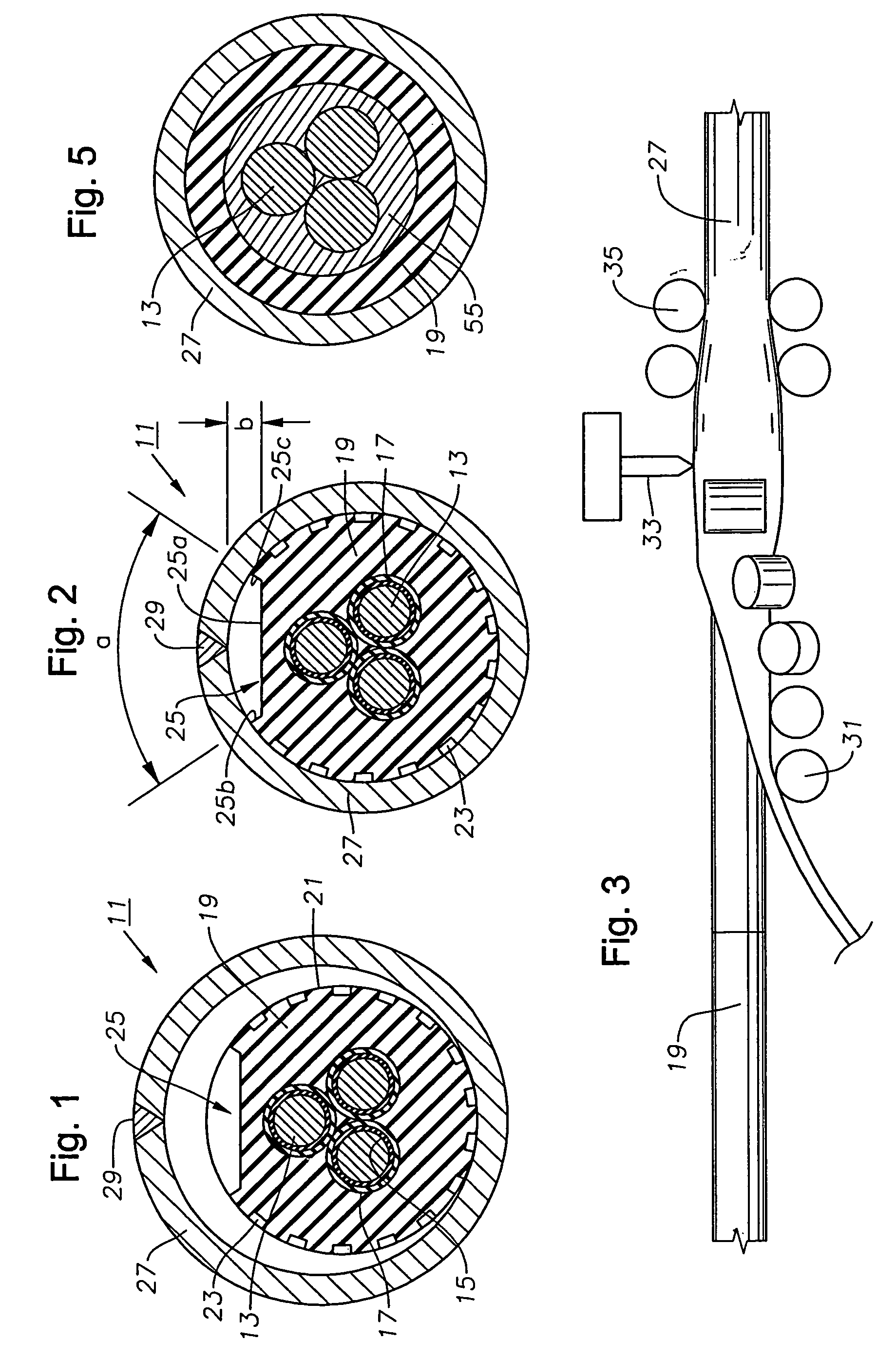
[0014]Referring to FIG. 1, heater cable 11 has a plurality of conductors 13. Conductors 13 are preferably fairly large copper wires, such as 6AWG. Each conductor 13 has at least one layer of high temperature electrical insulation and in the preferred embodiment, two layers 15, 17. Insulation layers 15, 17 maybe of a variety of materials, but must be capable of providing electrical insulation at temperatures of about 60 to 150 degrees F. above the bottom hole temperature of the well. In one embodiment, inner layer 15 is formed from a polyimide such as Kapton, marketed by DuPont. Outer layer 17 protects inner layer 15 and is formed of a fluoropolymer, preferably MFA, which is a co-polymer of tetrafluoroethylene and perfluoromethylvinylether. Layers 15 and 17 are formed on conductors 13 by extrusion.

[0015]The three insulator conductors 13 are twisted together and an elastomeric jacket 19 is extruded over them. Jacket 19 provides structural protection and also is an electrical insulator...


PUM

PropertyMeasurementUnit
outer diameteraaaaaaaaaa

Abstract

A method for manufacturing an electrical cable provides an electrical cable suitable for use in heating wells. An elastomeric jacket is extruded over insulated conductors. A stainless steel plate is rolled around the jacket to form a cylindrical coiled tubing having a seam. The seam is welded, then the tubing is swaged down to a lesser diameter to cause the tubing to frictionally grip the jacket. A recess maybe formed in the jacket adjacent the seam to avoid heat damage from the welding process.

Description

CROSS REFERENCE TO RELATED APPLICATION[0001]This application is a divisional of application Ser. No. 10 / 047,294, filed Jan. 14, 2002, now U.S. Pat. No. 6,695,062, which was a continuation-in-part of Ser. No. 09 / 939,902, filed Aug. 27, 2001, now U.S. Pat. No. 6,585,046.FIELD OF THE INVENTION[0002]This invention relates in general to applying heat to wells and in particular to a heater cable that is deployable while the well is live.BACKGROUND OF THE INVENTION[0003]Occasions arise wherein it is desirable to add heat to a hydrocarbon producing well. For example, U.S. Pat. No. 5,782,301 discloses a heater cable particularly for use in permafrost regions. The heater cable in that instance is used to retard the cooling of the hydrocarbon production fluid as it moves up the production tubing, which otherwise might cause hydrates to crystalize out of solution and attach themselves to the inside of the tubing. Also, if water is present in the production stream and production is stopped for a...

Claims


Application Information

Patent Timeline
Patent Type & Authority Patents(United States)
IPC IPC(8): E21B36/04E21B23/14H01B7/29H01B13/14
CPCE21B23/14H01B13/264E21B36/04Y10S174/33
Inventor DALRYMPLE, LARRY V.NEUROTH, DAVID H.WILBOURN, PHILLIP R.COX, DON C.WALLACE, THOMSON H.
Owner BAKER HUGHES INC
Why Eureka
Try Eureka