Ultrasonic diagnosis apparatus

a diagnostic apparatus and ultrasonic technology, applied in the field of ultrasonic diagnostic apparatus, can solve the problems of not reaching a practical use level, the present cfm mode has a difficulty in clearly displaying the pulsatility of blood flow in displaying its power, and the difficulty in clear discrimination of blood flow, etc., to achieve the effect of effectively displaying the pulsatility of blood vessel, simple and easy way

Inactive Publication Date: 2006-05-16
KK TOSHIBA
View PDF10 Cites 40 Cited by
  • Summary
  • Abstract
  • Description
  • Claims
  • Application Information

AI Technical Summary

Benefits of technology

[0025]The present invention has been made in consideration with the above problems, and an object of the present invention is to pro

Problems solved by technology

First, in recent years, as various types of diagnostic methods have been advanced, there are demands for a display technique that allows a user to identify a blood vessel as an artery, portal vein, or vein in a steadier and easier manner. In particular, to identify a blood vessel as described above by using an ultrasound wave, it is considered effective to observe pulsation appearing in blood flow.
Those methods have not, however, reached a level of practical use yet.
Besides, the present CFM mode has a difficulty to clearly display the pulsatility of blood flow in displaying its powe

Method used


Image

  • Ultrasonic diagnosis apparatus
  • Ultrasonic diagnosis apparatus
  • Ultrasonic diagnosis apparatus

Examples


first embodiment

[0091]An ultrasonic diagnosis apparatus according to a first embodiment of the present invention will now be described with reference to FIGS. 1 to 14.

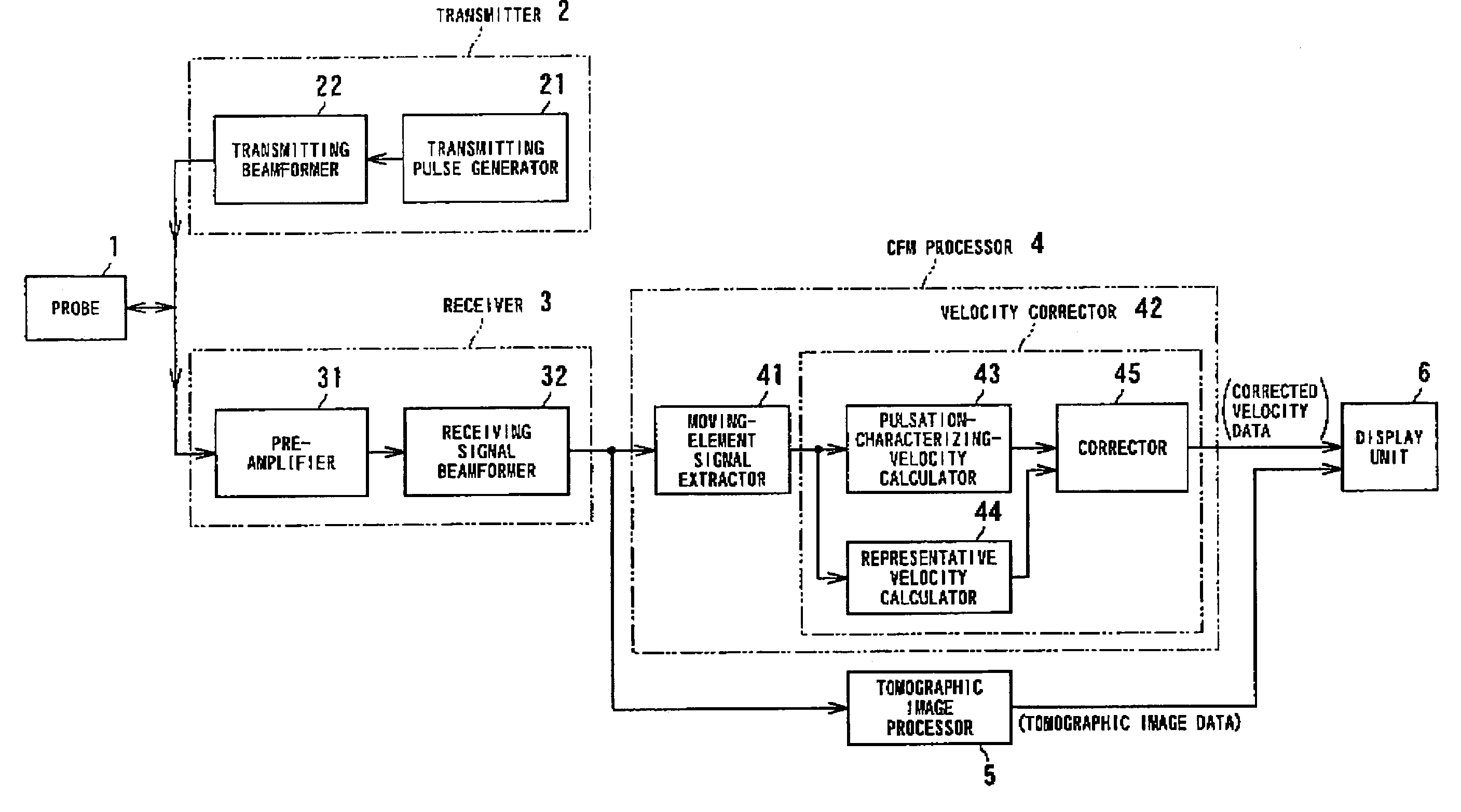
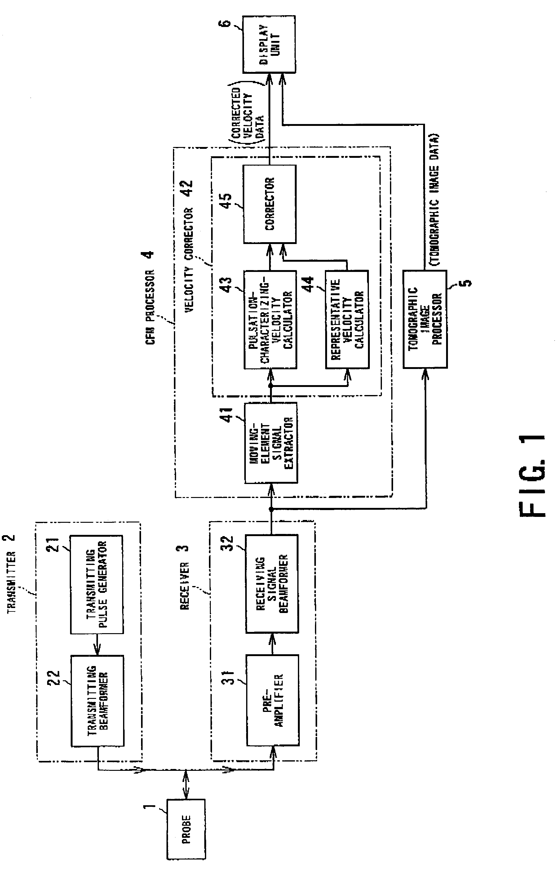
[0092]FIG. 1 is a functional block diagram depicting the configuration of the ultrasonic diagnosis apparatus according to this embodiment. As shown in FIG. 1, the ultrasonic diagnosis apparatus according to this embodiment comprises, in addition to an ultrasound probe 1 (hereinafter simply called “probe”) made to touch the surface of a subject to be examined, a transmitter 2 and a receiver 3 both electrically connected to the probe 1, a CFM processor 4 and a tomographic image (B-mode) processor 5 both electrically connected to the receiver 3, and a display unit 6 electrically connected to both of the processors 4 and 5.

[0093]The probe 1 includes a function of two-way conversion between an ultrasound signal and an electric signal. One example of the probe 1 is configured such that an array type of piezoelectric transducer is linearly s...

second embodiment

[0168]Referring to FIGS. 15 to 22, a second embodiment of the ultrasonic diagnosis apparatus according to the present invention will now be described. The present embodiment concerns a configuration in which the correction of the foregoing blood-flow Doppler signals is applied to three-dimensional display.

[0169]FIG. 15 shows the functional block diagram of the ultrasonic diagnosis apparatus that will be described below. As shown in FIG. 15, the ultrasonic diagnosis apparatus adopts a two dimensional array probe 7 as a probe made to touch to the surface of a subject to be examined.

[0170]As the remaining constituents, the ultrasonic diagnosis apparatus includes, as shown in FIG. 15, of a transmitter 2A and a receiver 3A, both of which are electrically connected to the two-dimensional array probe 7. The apparatus further includes a CFM processor and a topographic image processor 5, both of which are electrically connected to the receiver 3A, and a display unit 8 electrically connected ...


PUM


Abstract

An ultrasonic diagnosis apparatus comprises an ultrasound probe, a transmitter (including a transmitting pulse generator and a transmitting beamformer), a receiver (including a preamplifier and a receiving beamformer), a CFM processor (including a moving-element signal extractor and a velocity corrector), a tomographic image processor, and a display unit. The apparatus scans a desired section of a subject by transmitting and receiving an ultrasound pulse to and from the subject, and displays images obtained by the scanning. The velocity corrector comprises a pulsation-characterizing-velocity (velocities of a moving element) calculator, a representative velocity (reference velocity) calculator, and a corrector to correct the velocities of the moving element based on the standard velocity. The corrected velocity data is visualized on display unit. The ultrasonic diagnosis apparatus makes it possible to display the pulsatility of blood vessels in an easier and useful way.

Description

BACKGROUND OF THE INVENTION[0001]1. Field of the Invention[0002]The present invention relates to an ultrasonic diagnosis apparatus capable of not only effectively displaying dynamic states of flow of blood in a subject to be examined, particularly, pulsation of the flow of blood, but also three-dimensionally displaying pulsatile flows of blood in the subject.[0003]2. Description of Related Art[0004]An ultrasonic diagnosis apparatus has normally various types of displaying images, as has been widely known, which can be used for diagnosis on ultrasound images. Such types of displaying images include a CFM (Color Flow Mapping) mode used for displaying blood flow images, as well as tomographic image modes, such as a B-mode, used for displaying tomographic images.[0005]Among these modes, the CFM mode is prepared for displaying two-dimensional blood flow information in real time. In this mode, generally, flows of blood approaching to the ultrasound probe are displayed in red on a monitor,...

Claims


Application Information

Patent Timeline
IPC IPC(8): A61B8/02A61B8/06G01S7/52G01S15/58G01S15/89
CPCA61B8/06G01S7/52074A61B8/483G01S15/8988G01S15/8984
Inventor SHIKI, EIICHI
Owner KK TOSHIBA
Why Eureka
Try Eureka