
Thermophotovoltaic power generating apparatus

a technology of photovoltaic power generation and power generating equipment, which is applied in the direction of lighting and heating equipment, combustion types, machines/engines, etc., can solve the problem of not finding the optimal arrangement of components, and achieve the effect of reliably providing and uniformly reducing the photoelectric conversion elemen

Inactive Publication Date: 2006-05-16
TOYOTA JIDOSHA KK
View PDF20 Cites 3 Cited by
  • Summary
  • Abstract
  • Description
  • Claims
  • Application Information

AI Technical Summary

Benefits of technology

The invention is a thermophotovoltaic power generating apparatus that efficiently converts light into electricity. It includes a combustor, a porous emitter, a photoelectric conversion element, and a guide member. The combustor receives fuel and air for burning the fuel, and the porous emitter is heated by the combustion gas generated by the combustor. The photoelectric conversion element converts the light radiated from the porous emitter into electric power. The apparatus is designed to achieve stable combustion and efficient electric power generation. The invention also includes an exhaust port, a filter, and a pre-combustion chamber to improve the exhaust efficiency and stability of the combustion process. The apparatus can also include a pipe to supply air and fuel to the combustor, and a pipe to supply air to the filter to achieve uniform temperature reduction and stable combustion. Overall, the invention provides a more efficient and stable method for generating power using thermophotovoltaic technology.

Problems solved by technology

However, no optimal arrangement of those components has yet been determined.

Method used


Image

  • Thermophotovoltaic power generating apparatus
  • Thermophotovoltaic power generating apparatus
  • Thermophotovoltaic power generating apparatus

Examples


Embodiment Construction

[0031]Preferred embodiments of the invention will be described hereinafter with reference to the accompanying drawings.

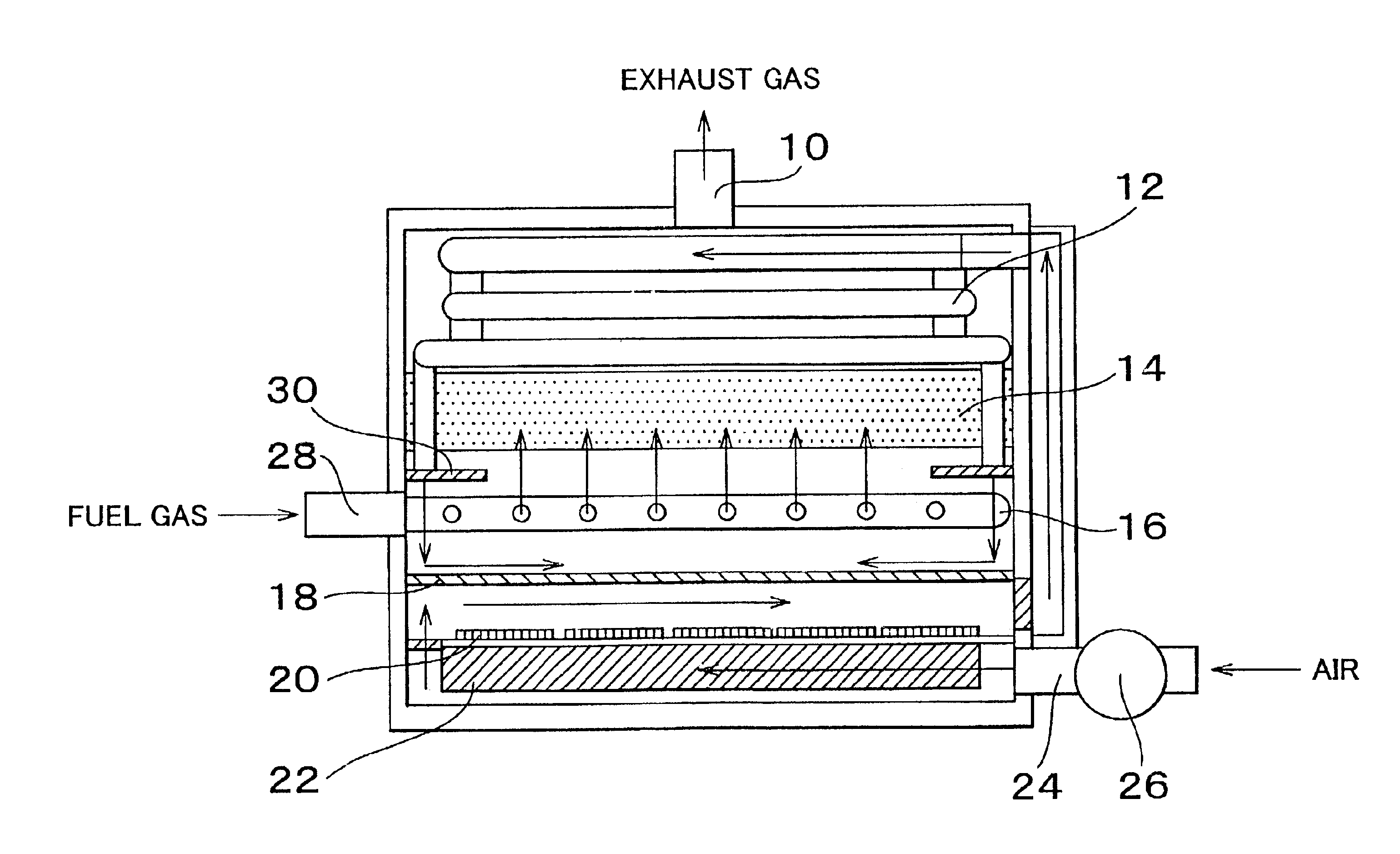
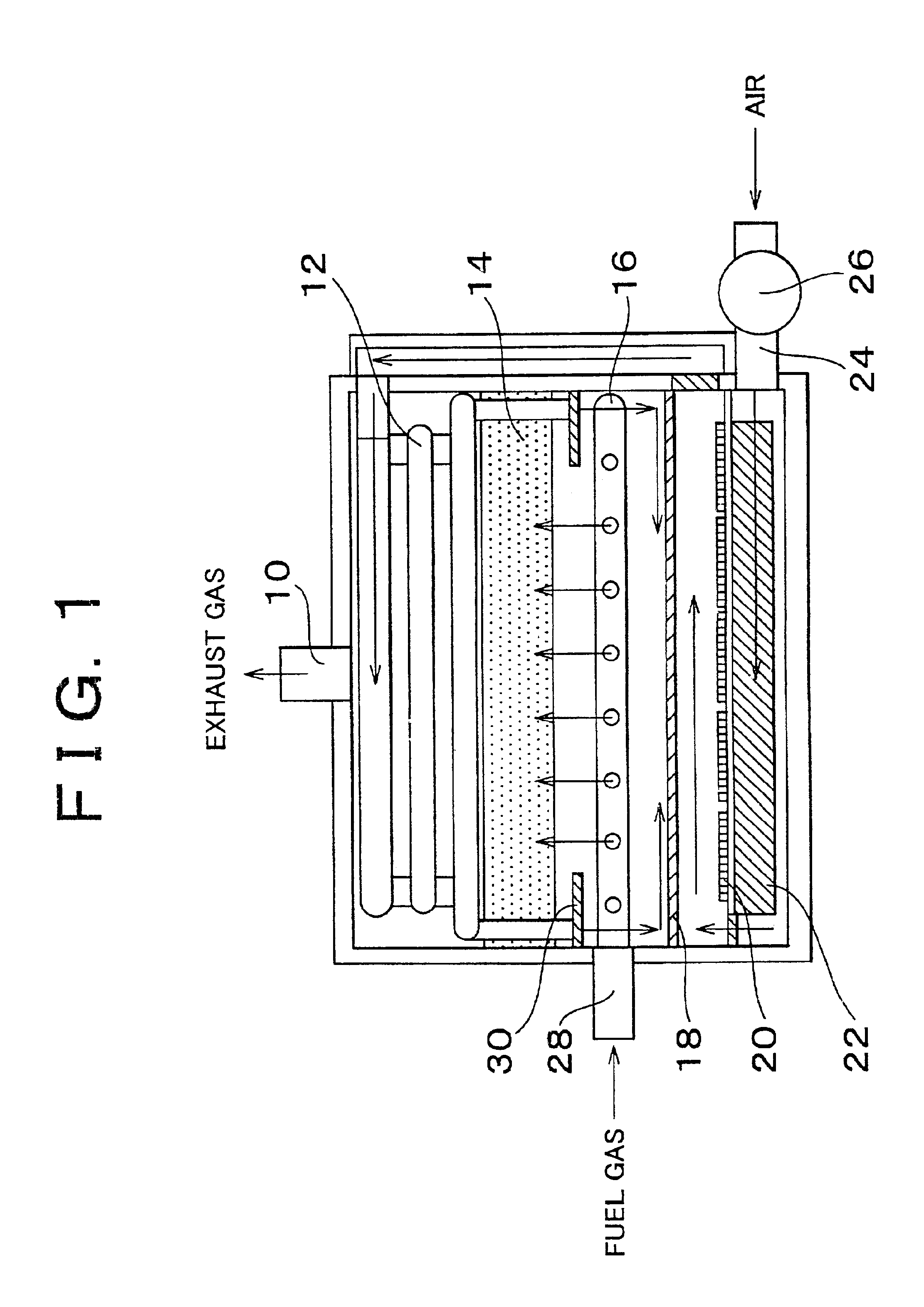
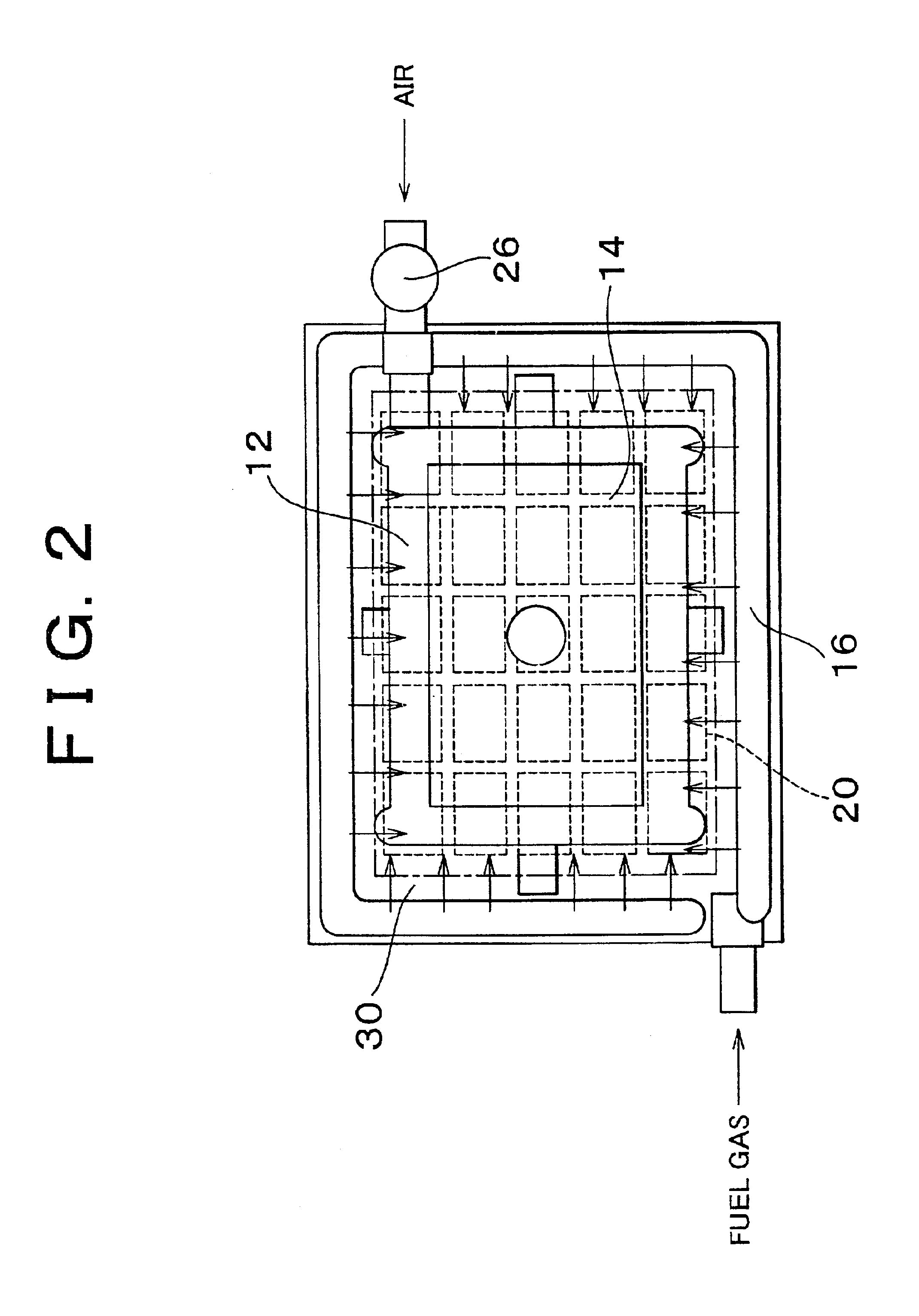
[0032]FIG. 1 is an elevation with a partial sectional view of a thermophotovoltaic power generating apparatus in accordance with a first preferred embodiment of the invention. FIG. 2 is a plan view with a partial sectional view of the thermophotovoltaic power generating apparatus of FIG. 1. This thermophotovoltaic power generating apparatus has a structure in which an exhaust pipe 10, a heat exchange portion 12, an emitter 14 of a porous material, a combustor (burner) 16, a wavelength selecting filter 18, and a plurality of photoelectric conversion cells 20 are arranged in that order from an upper side as shown in FIG. 1. A combustion chamber is defined by a space between the emitter 14 and the filter 18 where the combustor 16 is disposed.

[0033]Disposed below the photoelectric conversion cells 20 is a heat sink 22 for absorbing heat from the photoelectric conversion...


PUM


Abstract

A thermophotovoltaic power generating apparatus has a combustor for burning a fuel upon supply of the fuel and air, an emitter heated by passage therein of combustion gas produced in the combustor, and a photoelectric conversion element that converts light radiated from the emitter into electric power, the combustor being provided between the emitter and the conversion element. Preferably, the emitter is disposed above the combustor, and the photoelectric conversion element is disposed below the combustor. With this structure, combustion gas does not reside in the combustion chamber, but is discharged via the emitter disposed above the combustor. Combustion becomes stable, and the emitter is efficiently heated, so that energy radiated from the emitter surface increases.

Description

INCORPORATION BY REFERENCE[0001]The disclosure of Japanese Patent Application No. 2001-124801 filed on Apr. 23, 2001 including the specification, drawings and abstract is incorporated herein by reference in its entirety.BACKGROUND OF THE INVENTION[0002]1. Field of the Invention[0003]The invention relates to a thermophotovoltaic power generating apparatus (TPV system) for generating electric power through thermophotovoltaic energy conversion of infrared light (infrared ray, or heat ray) radiated from a heat source using a photoelectric conversion element (photoelectric conversion cell).[0004]2. Description of Related Art[0005]The thermophotovoltaic power generating apparatus causes an emitter to radiate infrared light of a constant wavelength by heating the emitter, and causes the infrared light to strike a photoelectric conversion element so that the infrared light is converted into electric power. The thermophotovoltaic power generating apparatus, having no movable portion, can be ...

Claims


Application Information

Patent Timeline
Patent Type & Authority Patents(United States)
IPC IPC(8): H01L31/00F03G7/00F23D14/12H01L31/058H01L31/04H01L31/042
CPCF23D14/125H02S10/30F23M2900/13004Y02E10/50
Inventor NAKAYAMA, HIDEKIMURATA, KIYOHITO
Owner TOYOTA JIDOSHA KK
Learn More