Power transformer/inductor

a technology of power transformers and transformers, applied in transformers/inductance coils/windings/connections, electrical equipment, basic electric elements, etc., can solve problems such as new problems that must be solved, and achieve good elasticity

Inactive Publication Date: 2006-05-16
ABB (SCHWEIZ) AG
View PDF762 Cites 18 Cited by
  • Summary
  • Abstract
  • Description
  • Claims
  • Application Information

AI Technical Summary

Benefits of technology

[0020]The use of such a cable implies that those regions of a transformer / inductor which are subjected to high electric stress are confined to the solid insulation of the cable. Remaining parts of the transformer / inductor, with respect to high voltage, are only subjected to very moderate electric field strengths. Furthermore, the use of such a cable eliminates several problem areas described under the background of the invention. Consequently a tank is not needed for insulation and coolant. The insulation as a whole also becomes substantially simple. The time of construction is considerably shorter compared to that of a conventional power transformer / inductor. The windings may be manufactured separately and the power transformer / inductor may be assembled on site.
[0031]Windings in the present invention are constructed to retain their properties even when they are bent and when they are subjected to thermal stress during operation. It is vital that the layers of the cable retain their adhesion to each other in this context. The material properties of the layers are decisive here, particularly their elasticity and relative coefficients of thermal expansion. In a XLPE-cable, for instance, the insulating layer is made of cross-linked, low-density polyethylene, and the semiconducting layers are made of polyethylene with soot and metal particles mixed in. Changes in volume as a result of temperature fluctuations are completely absorbed as changes in radius in the cable and, thanks to the comparatively slight difference between the coefficients of thermal expansion in the layers in relation to the elasticity of these materials, the radial expansion can take place without the adhesion between the layers being lost.
[0039]The conductivity of the two semiconducting layers is sufficient to substantially equalize the potential along each layer. The conductivity of the outer semiconducting layer is sufficiently large to contain the electrical field in the cable, but sufficiently small not to give rise to significant losses due to currents induced in the longitudinal direction of the layer.

Problems solved by technology

However, the use of such a cable presents new problems which must be solved.

Method used


Image

  • Power transformer/inductor
  • Power transformer/inductor
  • Power transformer/inductor

Examples


first embodiment

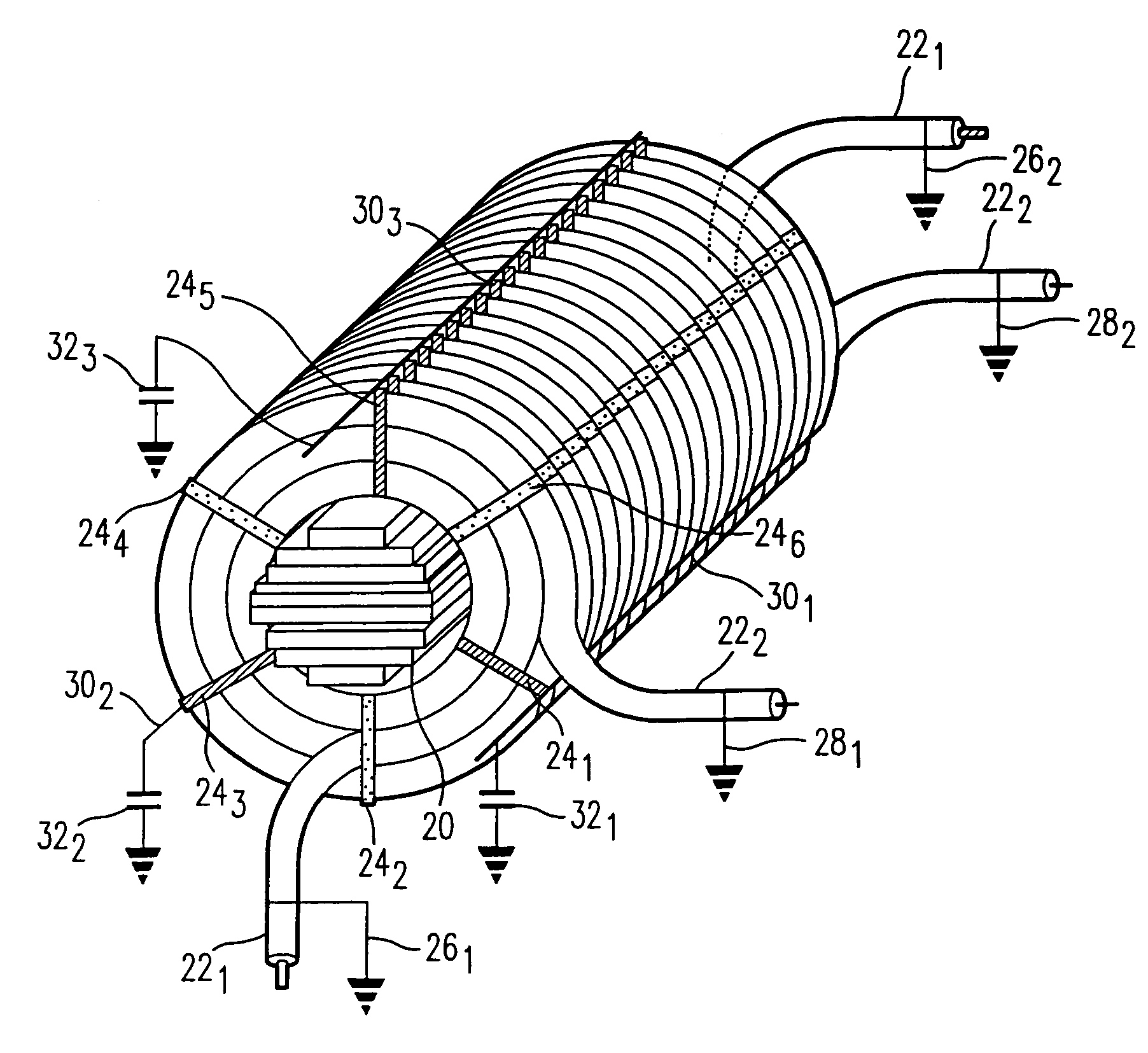
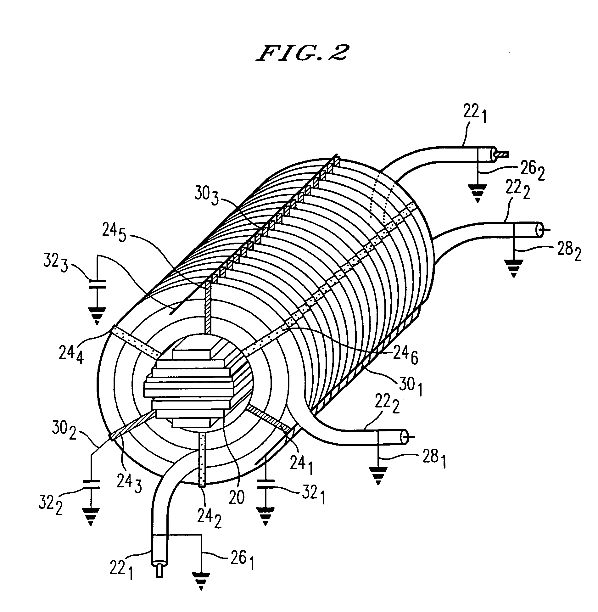
[0051]FIG. 2 shows a perspective view of windings with three indirect earthing points per winding turn according to the present invention. FIG. 2 shows a core leg designated by the numeral 20 within a power transformer or inductor. Two windings 221 and 222 are arranged around the core leg 20 which are formed from the high-voltage cable (10) shown in FIG. 1. With the aim of fixing windings 221 and 222 there are, in this case six radially arranged spacer members 241, 242, 243, 244, 245, 246, per winding turn. As shown in FIG. 2 the outer semiconducting layer is earthed at both ends 261, 262; 281, 282 of each winding 221, 222. Spacer members 241, 243, 245, which are emphasized in black, are utilised to achieve, in this case, three indirect earthing points per winding turn. The spacer member 241 is directly connected to a first earthing element 301, spacer member 243 is directly connected to a second earthing element 302 and spacer member 243 is directly connected to a third earthing el...

second embodiment

[0052]FIG. 3 shows a perspective view of windings with one direct earthing point and two indirect earthing points per winding turn according to the present invention. In FIGS. 2 and 3 the same parts are designated by the same numerals in order to make the Figures more clear. Also in this case the two windings 222 and 222, formed from the high-voltage cable 10 shown in FIG. 1, are ranged around the core leg 20. Windings 221, 222 are fixed by means of six spacer members 241, 242, 243, 244, 245, 246 per winding turn. At both ends 261, 262; 281, 282 of each winding 221, 222 the second semiconducting layer (compare with FIG. 1) is earthed in accordance with FIG. 2. Spacer members 241, 243, 245, which are marked in black, are used in order to achieve in this case one direct and two indirect earthing points per winding turn. In the same way as shown in FIG. 2 spacer member 241 is directly connected to a first earthing element 301, spacer member 243 is directly connected to a second earthin...

third embodiment

[0053]FIG. 4 shows a perspective view of windings with one direct earthing point and two indirect earthing points per winding turn according to the present invention. In FIGS. 2–4 the same parts are designated by the same numerals in order to make the Figures more clear. FIG. 4 shows windings 221, 222, a core leg 20, spacer members 241, 242, 243, 244, 245, 246 and earthing elements 301, 302, 303 arranged in the same way as shown in FIG. 3 and will therefore not be described in further detail here. Earthing element 301 is directly connected to earth, while earthing elements 302, 303 are indirectly earthed. Earthing elements 302, 303 are indirectly earthed in that they are connected in series via their own capacitor.


PUM

PropertyMeasurementUnit
diameteraaaaaaaaaa
areaaaaaaaaaaa
transmission voltagesaaaaaaaaaa

Abstract

A power transformer / inductor includes at least one winding. The winding is made of a high voltage cable that includes an electric conductor, and around the electric conductor is arranged a first semiconducting layer, around the first semiconducting layer is an insulating layer, and around the insulating layer is a second semiconducting layer. The second semiconducting layer is directly earthed at both ends of the winding and furthermore at least at two points per turn of every winding such that one or more points are indirectly earthed.

Description

CROSS REFERENCE TO RELATED APPLICATION[0001]This application is a continuation of application Ser. No. 09 / 355,795, filed Oct. 22, 1999.BACKGROUND OF THE INVENTION[0002]1. Field of the Invention[0003]The present invention relates to a power transformer / inductor.[0004]In all transmission and distribution of electric energy, transformers are used for enabling exchange between two or more electric systems normally having different voltage levels. Transformers are available for powers from the VA region to the 1000 MVA region. The voltage range has a spectrum of up to the highest transmission voltages used today. Electromagnetic induction is used for energy transmission between electric systems.[0005]Inductors are also an essential component in the transmission of electric energy in for example phase compensation and filtering.[0006]The transformer / inductor related to the present invention belongs to the so-called power transformers / inductors having rated outputs from several hundred kVA...

Claims


Application Information

Patent Timeline
Patent Type & Authority Patents(United States)
IPC IPC(8): H02H7/04H01F27/34H01F27/28
CPCH01F27/2828H01F27/288Y10S174/13H01F27/34
Inventor FROMM, UDOHORNFELDT, SVENHOLMBERG, PARKYLANDER, GUNNARMING, LILEIJON, MATS
Owner ABB (SCHWEIZ) AG
Why Eureka
Try Eureka