Core structure and interleaved DC-DC converter topology

Active Publication Date: 2006-05-16
MYPAQ HLDG LTD
View PDF12 Cites 122 Cited by
  • Summary
  • Abstract
  • Description
  • Claims
  • Application Information

AI Technical Summary

Benefits of technology

[0018]Each CDR preferably comprises first and second primary windings connected in series, and first and second secondary windings which are connected together at the output node, with the first and second secondary windings magnetically coupled to the first and second primary windings, respectively. The primary and secondary windings are preferably wound on a common core—preferably the novel core described herein. The AC drive voltages are applied a

Problems solved by technology

Transformers and inductors used within these power converters may be large and bulky and often limit their efficiency, power density and reliability.
One limitation on the area of the center leg is fringing flux.
Fringing flux causes current losses in the transformer of the other outer leg.
These two solutions result in either a wider E-core or a taller E-core, both of which can be burdens on mechanical designs.
Another problem with most E-cores arises from their inefficiency.
In general, the energy losses come in the form of heat.
This generated heat can become a sign

Method used


Image

  • Core structure and interleaved DC-DC converter topology
  • Core structure and interleaved DC-DC converter topology
  • Core structure and interleaved DC-DC converter topology

Examples


Embodiment Construction

[0037]Throughout this description, the embodiments and examples shown should be considered as exemplars, rather than limitations on the apparatus and methods of the present invention.

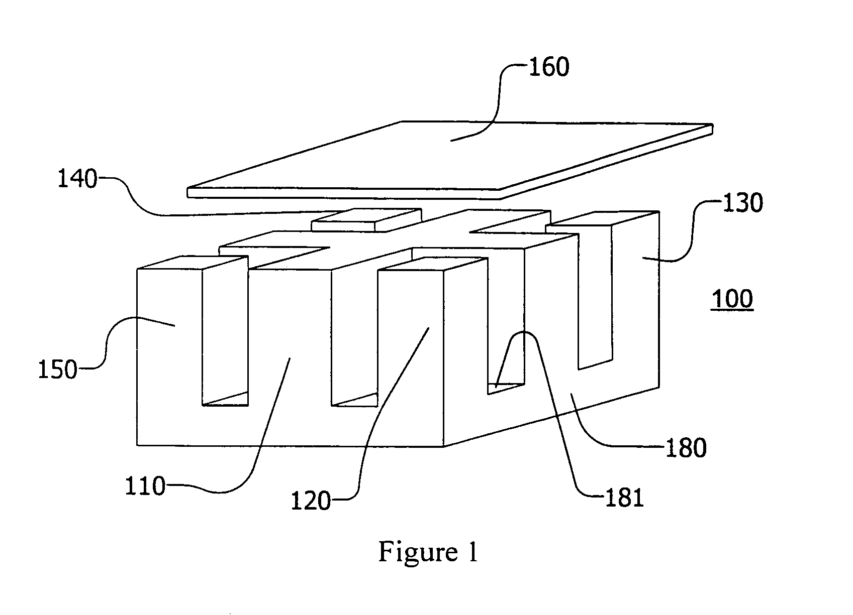
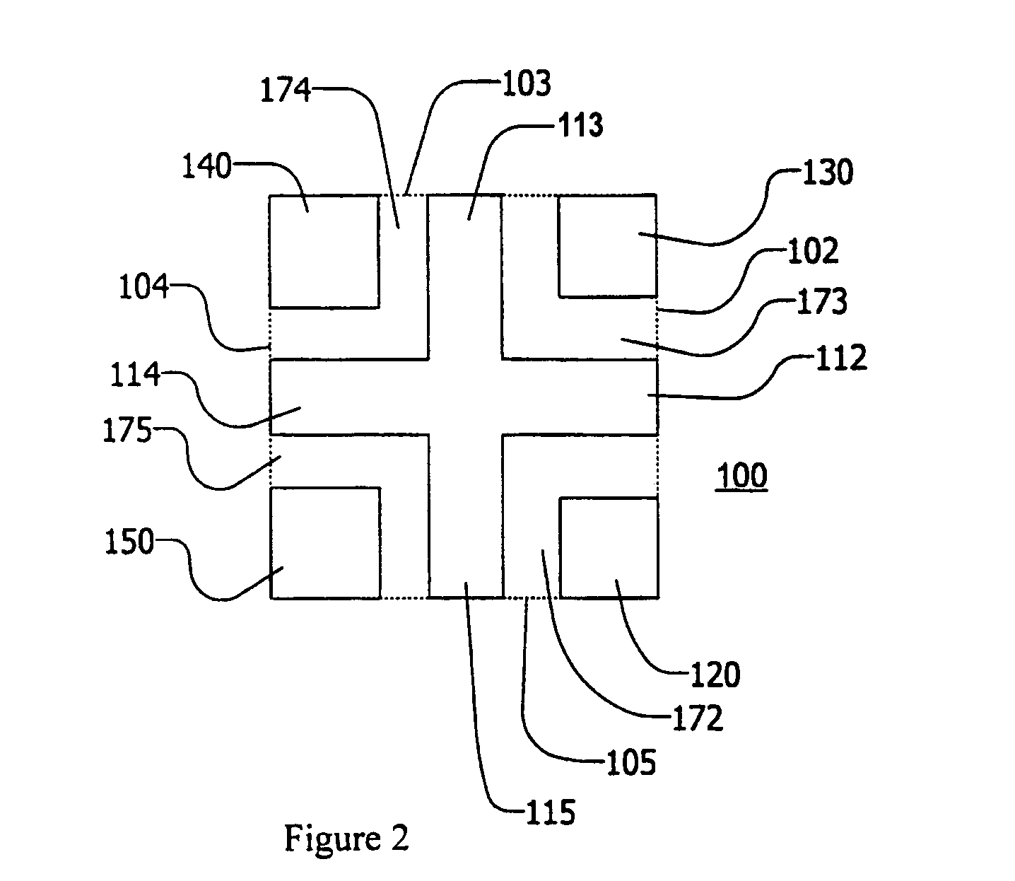
[0038]A core in accordance with the invention is useful in power modules and power converters. These power modules and power converters are well suited for low voltage, high current DC-DC converter applications. A core in accordance with the invention may have ultra-low profile magnetics, resulting in better utilization, higher inductance, improved efficiency and lower temperature. In typical E-cores, increased compactness results in decreased efficiency. In contrast, in a core of the invention, increased compactness may result in increased efficiency. Improved efficiency is an unexpected benefit of the invention.

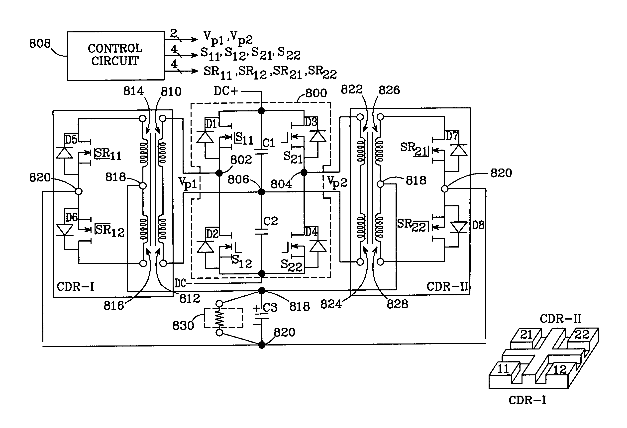
[0039]Principals of the invention are described below with respect to a half-bridge current doubler rectifier application. The invention is, however, applicable to a wide variety of DC-DC conve...


PUM


Abstract

There is disclosed a core structure with a very low profile, high power density and lower losses. The disclosed design allows for a larger core area where the DC fluxes are added, thereby reducing the air-gap requirements in the cores derived from low saturation density materials such as ferrites. The cellular nature of the design can be effectively employed in vertically packaged power converters and modules. Also disclosed is a DC-DC converter topology which preferably employs the disclosed core. N AC drive voltages drive N current doubler rectifiers (CDRs) in accordance with the symmetric modulation scheme; each CDR provides two rectified output currents to an output node. Each AC drive voltage has a switching period Ts. The drive voltages are phase-shifted by Ts/(2*N), such that the rectified output currents of the CDRs are interleaved, thereby reducing output voltage ripple.

Description

CROSS-REFERENCE TO RELATED APPLICATIONS[0001]This application is a continuation-in-part of application Ser. No. 10 / 126,477, filed Apr. 18, 2002 now U.S. Pat. No. 6,873,237.NOTICE OF COPYRIGHTS AND TRADE DRESS[0002]A portion of the disclosure of this patent document contains material which is subject to copyright protection. This patent document may show and / or describe matter which is or may become trade dress of the owner. The copyright and trade dress owner has no objection to the facsimile reproduction by any one of the patent disclosure as it appears in the Patent and Trademark Office patent files or records, but otherwise reserves all copyright and trade dress rights whatsoever.GOVERNMENT INTERESTS[0003]The United States Government has rights in this invention pursuant to Contract No. 48803-8101 (RC) and 44104-8901 (Govt.) between the United States Department of Defense, Office of Naval Research and Rockwell Scientific Co.BACKGROUND OF THE INVENTION[0004]1. Field of the Inventi...

Claims


Application Information

Patent Timeline
IPC IPC(8): H02M3/335H02M7/5387H02M5/42H01F3/08H01F17/04H01F30/06H02M7/04
CPCH01F3/08H02M7/043H01F30/06H01F17/04
Inventor SUN, JIANJING, XIUKUANCHANDRASEKARAN, SRIRAMMEHROTRA, VIVEK
Owner MYPAQ HLDG LTD
Why Eureka
Try Eureka