Optical disk apparatus and method for adjusting tilt based on optical disk type
- Summary
- Abstract
- Description
- Claims
- Application Information
AI Technical Summary
Benefits of technology
Problems solved by technology
Method used
Image
Examples
Embodiment Construction
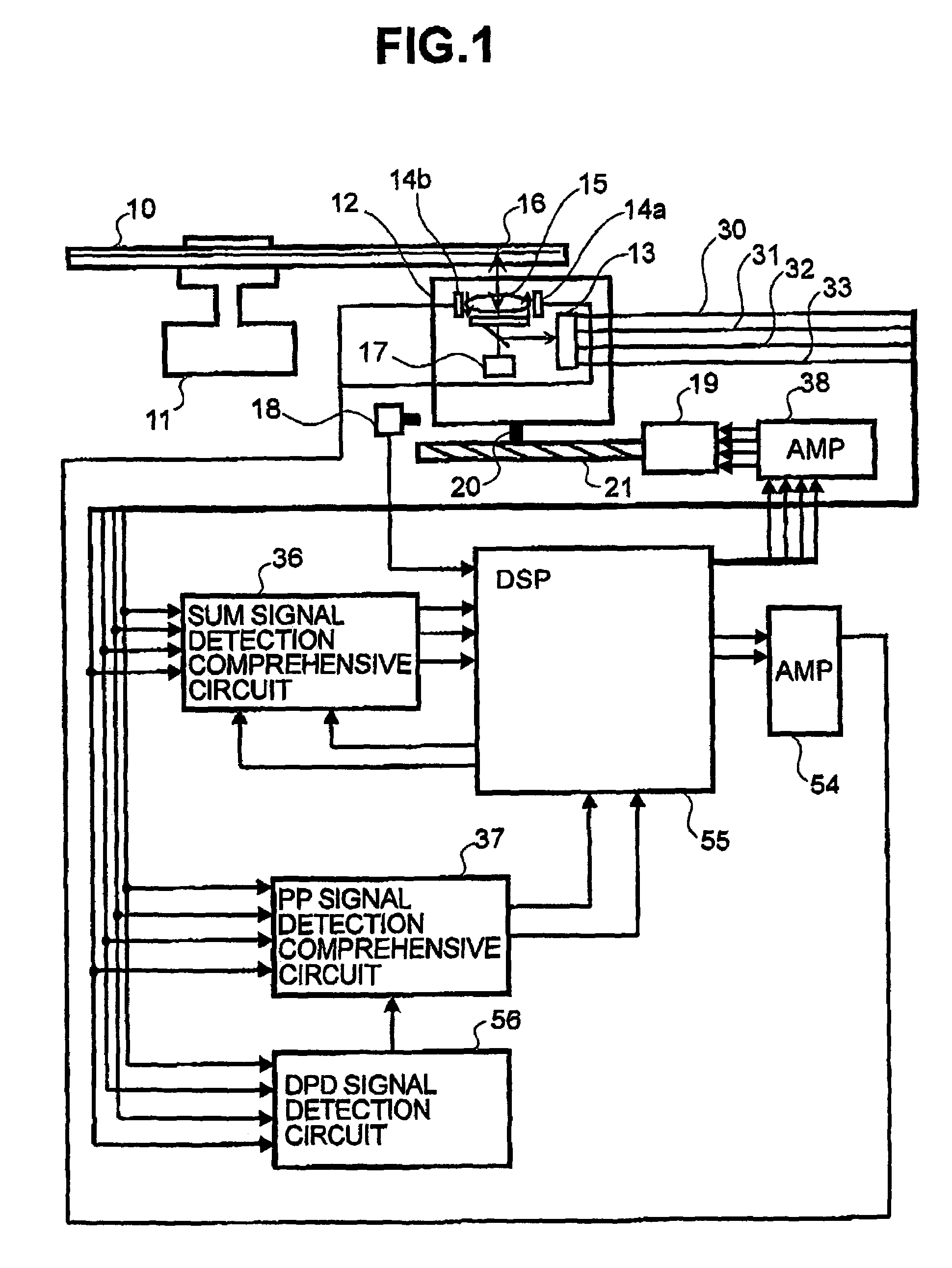
[0029]FIG. 1 is a schematic block diagram showing an optical disk apparatus according to one embodiment of the present invention. In the figure, reference numeral 10 denotes an optical disk, and numeral 11 denotes a spindle motor. The optical disk 10 is attached to the spindle motor 11 and rotated. Reference numeral 12 denotes an optical pickup for recording / reproducing information to / from the disk. Reference numeral 19 denotes a stepping motor; numeral 20 a pin fixed to the optical pickup 12; and numeral 21 a shaft of the stepping motor 19 in which a helical groove is formed thereon. The stepping motor 19, the pin 20, and the shaft 21 collectively constitute an advance mechanism for the optical pickup 12. The pin 20 is inserted in the groove of the shaft 21 so that the pin 20 can be moved along the groove. The stepping motor 19 causes the shaft 21 to rotate. As the shaft 21 rotates, the position of the pin 20 in the groove moves radially with respect to the disk, moving the pickup ...
PUM
 Abstract
Description
Claims
Application Information
 - R&D
- Intellectual Property
- Life Sciences
- Materials
- Tech Scout
- Unparalleled Data Quality
- Higher Quality Content
- 60% Fewer Hallucinations
Browse by: Latest US Patents, China's latest patents, Technical Efficacy Thesaurus, Application Domain, Technology Topic, Popular Technical Reports.
© 2025 PatSnap. All rights reserved.Legal|Privacy policy|Modern Slavery Act Transparency Statement|Sitemap|About US| Contact US: help@patsnap.com


