Proximity effect correction apparatus, proximity effect correction method, storage medium, and computer program product

a technology of proximity effect and correction apparatus, which is applied in the direction of photomechanical apparatus, instruments, printing, etc., can solve the problems of difficult to be represented by the rule, the definition of the correction rule is limited, and the design of the semiconductor circuit cannot be manufactured

Inactive Publication Date: 2006-05-16
MIE FUJITSU SEMICON
View PDF10 Cites 38 Cited by
  • Summary
  • Abstract
  • Description
  • Claims
  • Application Information

AI Technical Summary

Benefits of technology

[0017]The present invention is directed to an apparatus, a method, a storage medium, and a computer program product for automatically correcting a proximity effect in exposing a mask pattern by lithography.
[0018]In the proximity effect correction method of the present invention, light intensity values only of the vicinity of a specified portion, which are necessary for correcting a proximity effect in an object to be corrected, are calculated and the object to be corrected is corrected based on the light intensity values.
[0019]In exposing the mask pattern by lithography, when the mask pattern being the object to be corrected has a desired form, the proximity effect correction method of the present invention includes a first step of judging, based on a prescribed value, a side of the object to be corrected existing near an area where the distance between in the object of the desired form is equal to or shorter than the prescribed value as a portion to be correct, a second step of calculating light intensity values only of the vicinity of the portion to be corrected, and a third step of correcting the object to be corrected based on the calculated light intensity values.
[0020]When the mask pattern being the object to be corrected does not have the desired form, the proximity effect correction method of the present invention includes a first step of judging, based on a prescribed value, a side of the object to be corrected existing near an area where the distance between edges in an object of the desired form is equal to or shorter than the prescribed value as a portion where the proximity effect is to be corrected, a second step of calculating light intensity values only on the object of the desired form in a predetermined range near the portion to be corrected, and a third step of correcting the object to be corrected based on the calculated light intensity values.

Problems solved by technology

This influence of the proximity effect has brought about a problem that a semiconductor circuit as designed cannot be manufactured.
However, the definition of the correction rule is limited and a complicated form and the like are difficult to be represented by the rule.
As described above, an optimal form for proximity effect correction can be derived by simulating an exposure result at every necessary time if the simulator is used but, on the other hand, there is a problem that correction processing takes long time and it is unrealistic in terms of processing time to obtain the light intensity distribution for all the regions of an enormous amount of design data.
Further, any method for performing appropriate proximity effect correction is not provided currently for a case in which the object to be corrected does not have the desired form.

Method used


Image

  • Proximity effect correction apparatus, proximity effect correction method, storage medium, and computer program product
  • Proximity effect correction apparatus, proximity effect correction method, storage medium, and computer program product
  • Proximity effect correction apparatus, proximity effect correction method, storage medium, and computer program product

Examples


specific embodiments

[0036]Hereinafter, based on the basic essence of the present invention described above, specific embodiments to which the present invention is applied will be explained in detail with reference to the drawings.

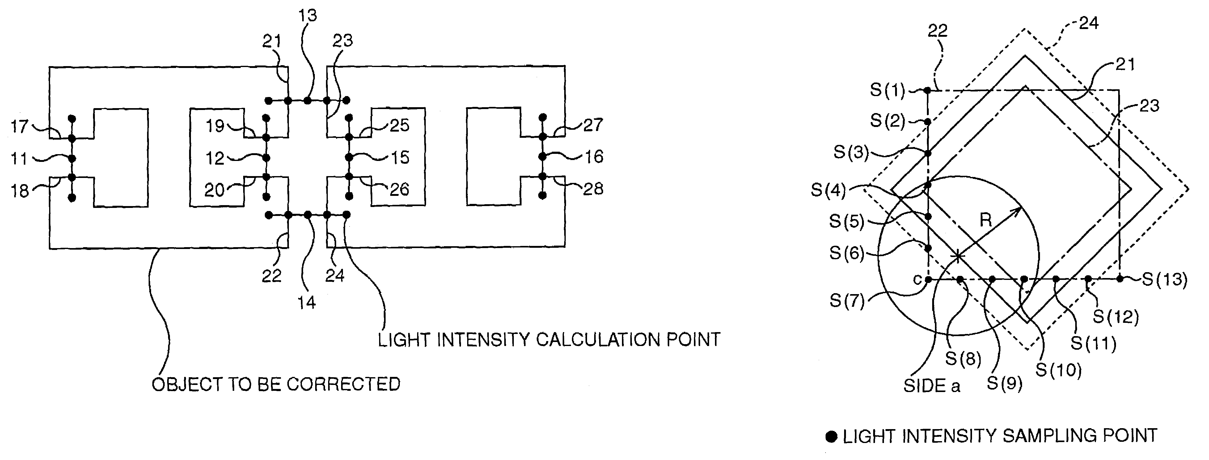
[0037]A proximity effect correction apparatus in each embodiment below has, as a main component, a means for calculating light intensity values only of the vicinity of a specified portion, which are necessary for correcting a proximity effect in an object to be corrected, and correcting the object to be corrected based on the light intensity values.

first embodiment

[0038]This embodiment is directed to proximity effect correction in exposing a mask pattern by lithography when an object to be corrected coincides with a desired form (target object) to be realized by exposing the mask pattern.

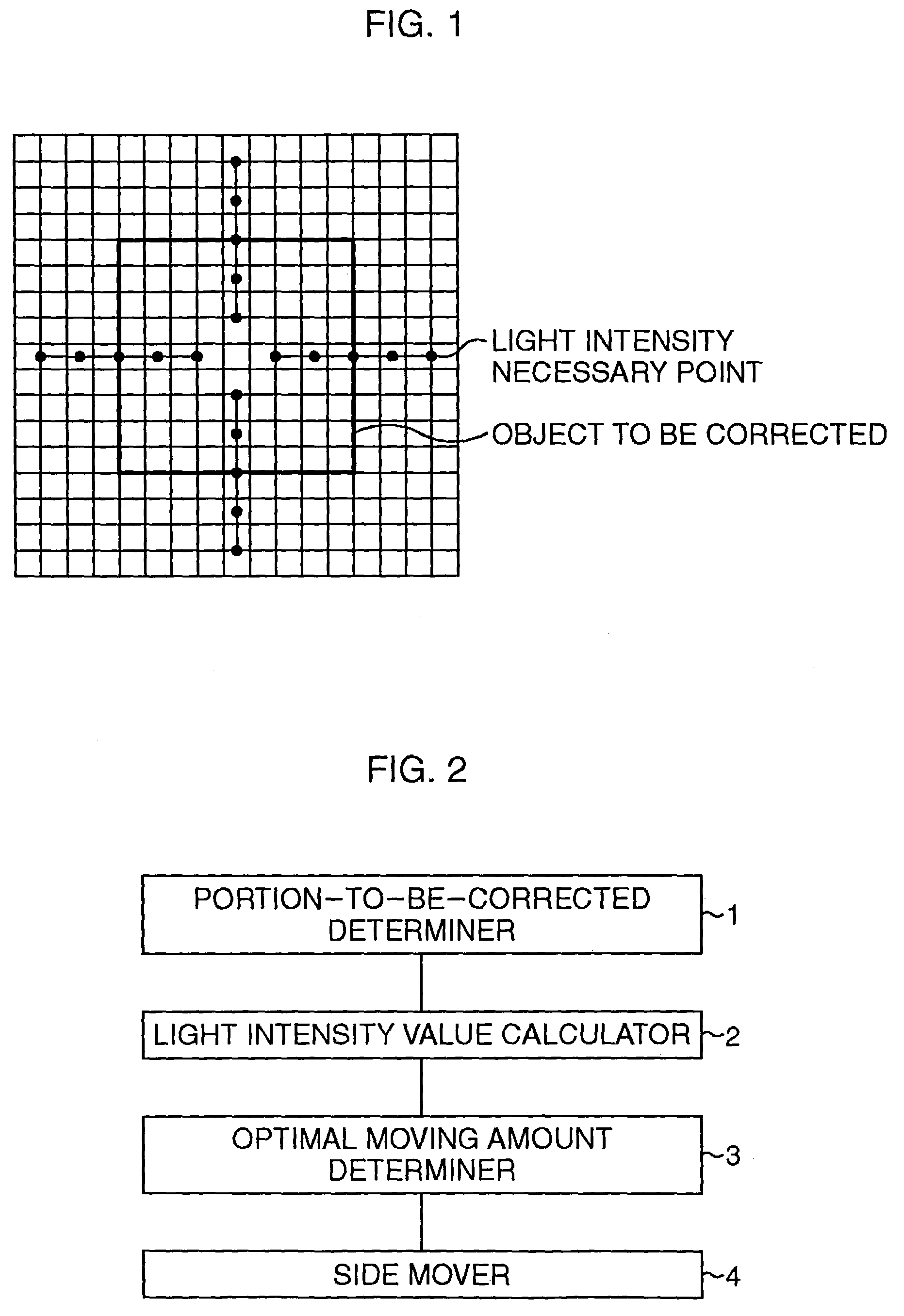
[0039]FIG. 2 is a block diagram showing the schematic structure of a proximity effect correction apparatus according to this embodiment.

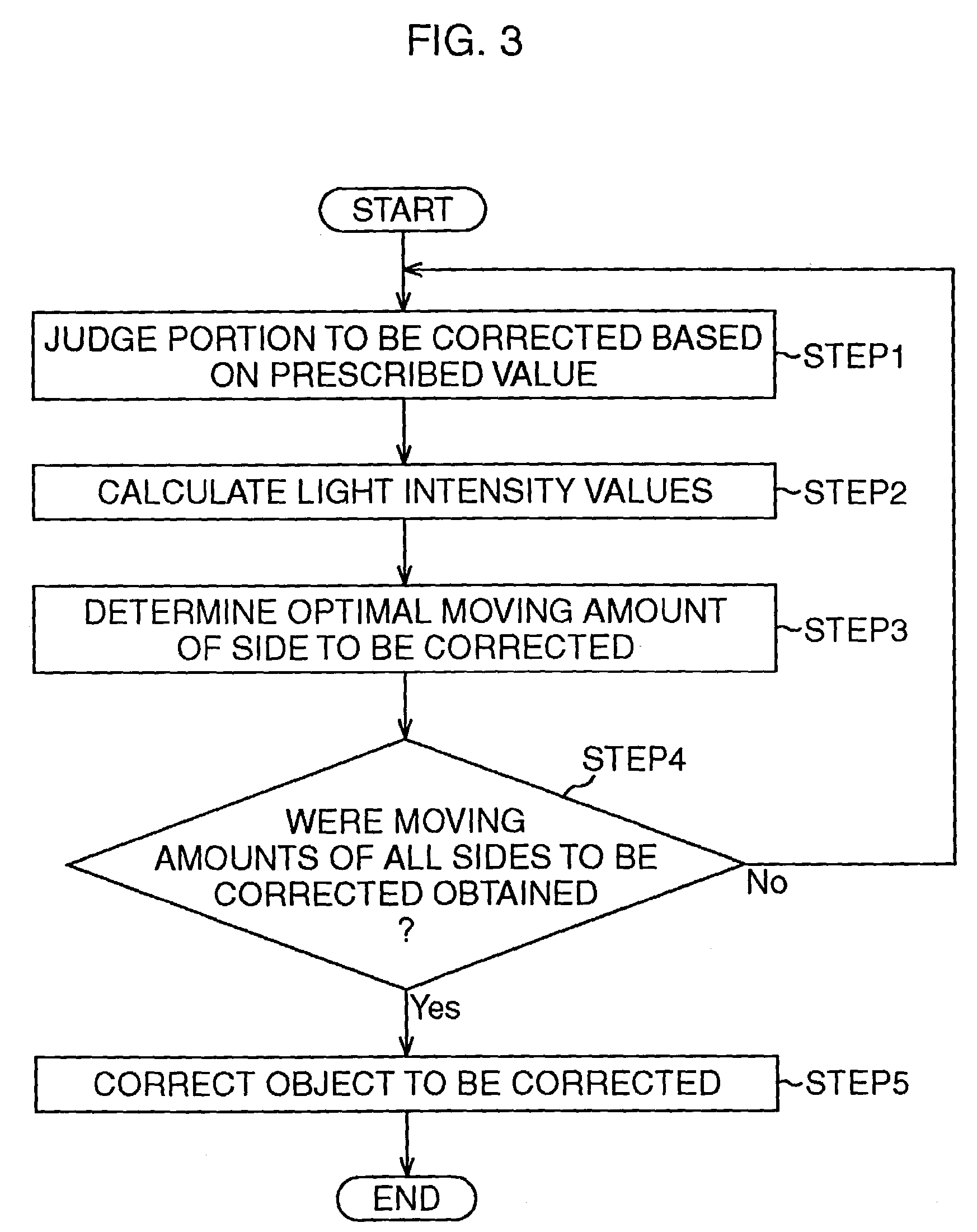
[0040]The proximity effect correction apparatus is structured to have a portion-to-be-corrected determiner 1 for judging, based on a prescribed value, a side of an object to be corrected existing near an area where the distance between edges in an object of a desired form is equal to or shorter than the prescribed value as a portion where a proximity effect is to be corrected, a light intensity value calculator 2 for calculating light intensity values only on the object of the desired form in a predetermined range near the portion to be corrected, an optimal moving amount determiner 3 for determining an optimal moving amount ...

second embodiment

[0048]This embodiment is directed to proximity effect correction in performing exposure of a mask pattern by lithography when an object to be corrected does not have a desired form (target object) to be realized by exposing the mask pattern.

[0049]FIG. 6 is a block diagram showing the schematic structure of a proximity effect correction apparatus according to this embodiment.

[0050]The proximity effect correction apparatus is structured to have a portion-to-be-corrected determiner 11 for judging, based on a prescribed value, a side of an object to be corrected existing near an area where the distance between edges in an object of a desired form is equal to or shorter than the prescribed value as a portion where a proximity effect is to be corrected, a light intensity value calculator 12 for calculating light intensity values only on the object of the desired form in a predetermined range near the portion to be corrected, an optimal moving amount determiner 13 for determining an optima...


PUM

PropertyMeasurementUnit
lengthaaaaaaaaaa
lengthaaaaaaaaaa
proximity effect correctionaaaaaaaaaa

Abstract

Light intensity values only of the vicinity of a specified portion, that is, for example, based on a prescribed value, an area where the distance between edges of an object to be corrected is equal to or shorter than the prescribed value are calculated, and the object to be corrected is corrected based on the light intensity values.

Description

CROSS-REFERENCE TO RELATED APPLICATIONS[0001]This application is based upon and claims the benefit of priority from the prior Japanese Patent Application No. 2002-060775, filed on Mar. 6, 2002, the entire contents of which are incorporated herein by reference.BACKGROUND OF THE INVENTION[0002]1. Field of the Invention[0003]The present invention relates to an apparatus, a method, a storage medium, and a computer program product for performing proximity effect correction in exposing a mask pattern by lithography.[0004]2. Description of the Related Art[0005]A demand for a finer semiconductor circuit has been recently increasing and an influence of a proximity effect as a result of making the circuit finer is becoming a matter which is not negligible. This influence of the proximity effect has brought about a problem that a semiconductor circuit as designed cannot be manufactured. Accordingly, processing called proximity effect correction is performed in which the influence of the proxim...

Claims


Application Information

Patent Timeline
Patent Type & Authority Patents(United States)
IPC IPC(8): G06F17/50G03C5/00G06F1/00G06K9/00G03F1/36G03F1/68G03F7/20H01L21/027H01L21/82
CPCG03F1/144G03F7/70441G03F1/36
Inventor FUTATSUYA, HIROKI
Owner MIE FUJITSU SEMICON
Why Eureka
Try Eureka