Method and apparatus for equalizing video transmitted over twisted pair cable

Active Publication Date: 2006-05-16
RGB SYST INC
View PDF4 Cites 36 Cited by
  • Summary
  • Abstract
  • Description
  • Claims
  • Application Information

AI Technical Summary

Benefits of technology

[0033]This invention defines a method and apparatus for enhancing or improving the quality of high-resolution video images by compensating for the losses caused by transmission of the video signal over long twisted pair cables. The loss that occurs during transmission of the video signal is known as cable insertion loss. Transmission of video over twisted pair cable is advantageous because of its superior cost advantage over coaxial cable. However, twisted pair cables have significant loss characteristics at the higher frequencies (i.e., broadband) compared to coaxial cables. In one embodiment of the invention, the video signal is pre-compensated at a transmitter station for possible skin effect losses before being injected into the twisted pair line for transmission to a receiver station. The pre-compensation at the transmitter station amplifies the high frequency region to brute force the high frequency signals to the receiver station. Amplifying the high frequency spectrum of the video at the transmitter station prevents boosting of noise that may have been picked-up during transmission over the twisted pair cables to the receiver station, which may be up to 1000 feet from t

Problems solved by technology

However, twisted pair cables have significant loss characteristics at the higher frequencies (i.e., broadband) compared to coaxial cables.
Thus, at the receiving station, the high frequency compensation

Method used


Image

  • Method and apparatus for equalizing video transmitted over twisted pair cable
  • Method and apparatus for equalizing video transmitted over twisted pair cable
  • Method and apparatus for equalizing video transmitted over twisted pair cable

Examples


Embodiment Construction

[0054]An embodiment of the invention comprises a method and apparatus for equalization of video transmitted over long twisted pair cables. In the following description, numerous specific details are set forth to provide a more thorough description of embodiments of the invention. It will be apparent, however, to one skilled in the art, that the invention may be practiced without these specific details. In other instances, well known features have not been described in detail so as not to obscure the invention.

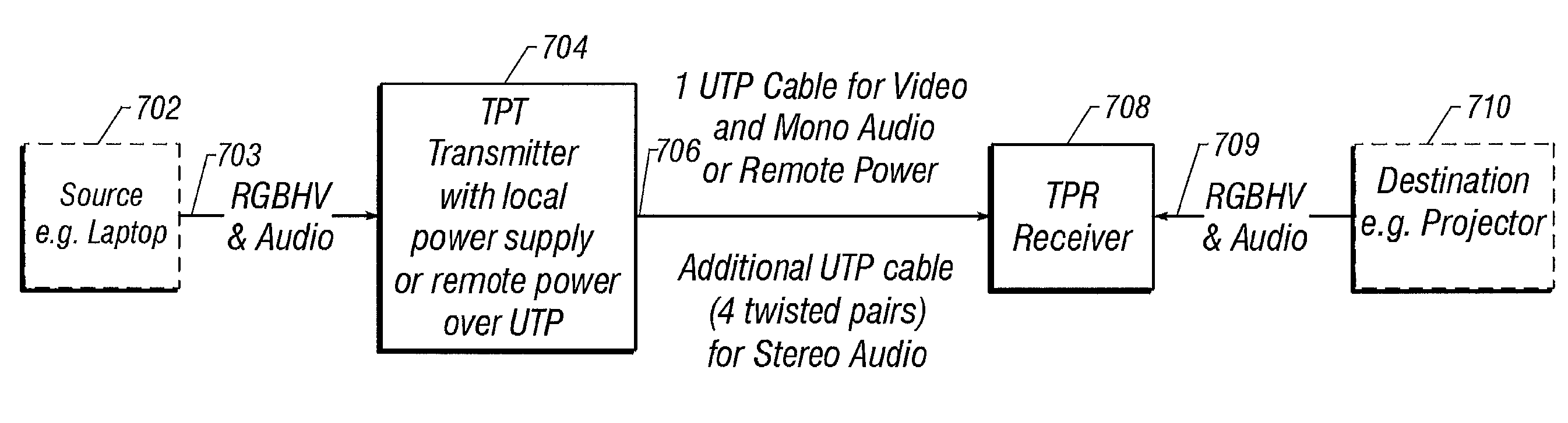
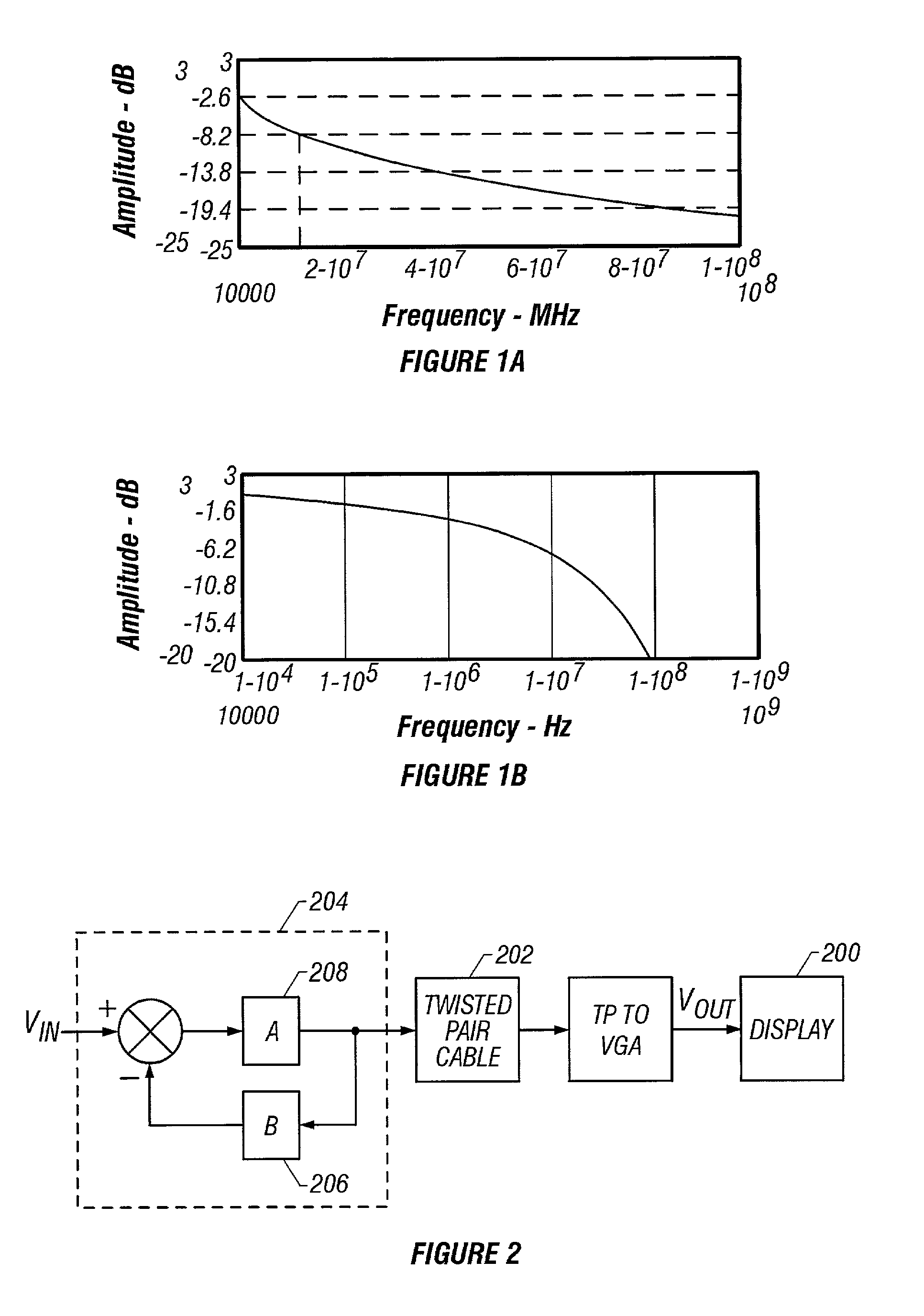
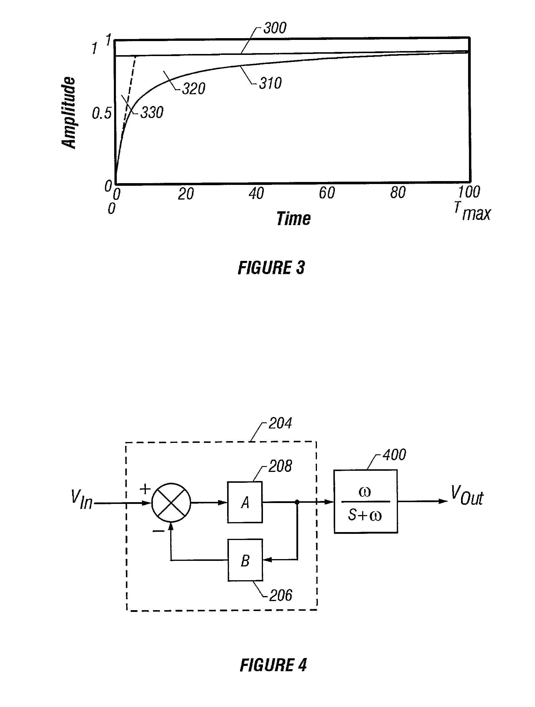
[0055]An embodiment of the invention provides a method and apparatus for enhancing and improving the quality of video images by compensating for the loss and other effects of transmitting video over a medium such as twisted pair cables. For instance, one embodiment of the invention uses a configuration consisting of compensation for the diffusion effects, skin effects, and skew due to dissimilarities between different cable pairs.

[0056]FIG. 7 is a functional block diagram illus...


PUM


Abstract

A apparatus and apparatus for compensating for video insertion loss due to transmission over long twisted pair cable lines is presented. Transmission of video over twisted pair cable is advantageous because of its superior cost advantage over coaxial cable. However, twisted pair cables have significant loss characteristics at the higher frequencies (i.e., broadband) compared to coaxial cables. At a transmitter station, the video signal is amplified in the high frequency region for possible skin effect losses thereby brute forcing the high frequency components to the receiving station. At the receiver station, the video signal is further compensated for diffusion line and skin effect losses. The total skin effect compensation applied in both the transmitter and receiver stations is such that the square root of frequency characteristics of skin effect losses is compensated for. Thus, at the receiving station, the high frequency compensation added at the transmitter to brute force the high frequency components to the receiving station may be removed if found excessive. Additionally, compensation is included to adjust for skew that may occur because of irregularities between the various twisted pairs used to transmit the individual video components. Non-minimum phase type filters are used to inject delay into the faster arriving signals so that they may coincide in phase with later arriving signals resulting in a true reproduction of the video.

Description

BACKGROUND OF THE INVENTION[0001]1. Field of the Invention[0002]This invention relates to the field of video insertion loss equalization. More specifically the invention relates to compensating for losses in analog video quality due to transmission over twisted pair cable.[0003]2. Background Art[0004]Video cables are used to convey electronic video signals from a source device such as a receiver to a destination, typically a display device. A cable is supposed to accurately convey the signal, however, losses accumulate along the cable path because of imperfections in a transmission cable. These imperfections are not necessarily due to manufacturing but due to the fact that a cable is a physical device and most physical devices exhibit some losses when a signal is conveyed through them. Thus, the longer the cable length, the more losses accumulate. The accumulated transmission loss is known by those of skill in the art as cable insertion loss. Of course, other devices such as switche...

Claims


Application Information

Patent Timeline
IPC IPC(8): H04N7/16H04N7/10
CPCH04N7/108Y10S348/914
Inventor COLE, GARY DEANSCHNEIDER, MANFREDGARCIA, ARTANDREWS, MIKE A.
Owner RGB SYST INC
Why Eureka
Try Eureka