Adaptive flap and slat drive system for aircraft

a technology of adaptive flaps and drive systems, which is applied in the direction of aircraft power plants, power amplification, transportation and packaging, etc., can solve the problems of high friction, high installation effort and expense, and the failure to control could have catastrophic consequences for the overall control and flight safety of the aircraft, so as to reduce the friction acting, simplify the maintenance of the flap system, and reduce the installation effort.

Active Publication Date: 2006-05-23
AIRBUS OPERATIONS GMBH
View PDF19 Cites 125 Cited by
  • Summary
  • Abstract
  • Description
  • Claims
  • Application Information

AI Technical Summary

Benefits of technology

[0010]In view of the above, it is an object of the invention to provide an improved drive system for flaps and / or slats of a fixed wing aircraft, which increases the availability of the flap functions in the event of a failure or malfunction, and increases the functional flexibility and adaptability of the flap system, in comparison to the prior art systems. The invention further aims to avoid or overcome the disadvantages of the prior art, and to achieve additional advantages, as apparent from the present specification. The attainment of these objects is, however, not a required limitation of the invention.
[0013]In a further arrangement or embodiment according to the invention, a plurality of flaps or slats is grouped together as a flap / slat body group, and at least two drives forming a drive station are allocated to this flap / slat body group. Each of these drives is respectively connected mechanically through a respective drive transmission to an associated flap or slat of the group. The two drives are both mechanically coupled to a rotational shaft extending between the drives. Additionally, guide transmissions are coupled to the shaft at positions between the two drives, and are connected to flaps or slats of the flap / slat body group for additionally actuating the respective connected flap or slat. Thus, each flap or slat of the group will be connected to and driven by either one drive and one guide transmission, or two guide transmissions. In this manner, i.e. with these arrangements, if one of the drives or one of the guide transmissions should fail, then drive power can still be delivered to each slat or flap of the respective group by the remaining functional drive or drives, the rotational shaft, and the remaining functional guide transmissions. In other words, each one of these arrangements involves at least two drives driving the rotational shaft, and at least two power transmissions (i.e. either two guide transmissions or one guide transmission and one drive transmission) connected to each flap or slat of the group. This provides redundancy in the event of the failure of one of the drives or one of the transmissions. Thus, in the event of a possible failure of one of the drives, of one of the transmissions, or even a shaft break of the drive shaft, the actuation, control, and monitoring functions of the flap system will not be substantially limited thereby, and will not lead to a total failure of the flap system.
[0014]The above arrangements further allow the independent and individual actuation of each group of flaps or slats, and also the independent and individual actuation of the flaps or slats on the left wing relative to the flaps or slats on the right wing of the aircraft. A further advantage is that avoiding a long transmission shaft typical in the prior art reduces the dynamic problems associated therewith, and also reduces the friction acting on the shaft, the drives and the overall flap system. Also, the installation effort, complexity and expense is reduced, and the maintenance of the flap system is simplified.

Problems solved by technology

Such a lack of control could have catastrophic consequences for the overall control and flight safety of the aircraft.
Furthermore, such conventional flap systems including a central drive and a rather long continuous transmission shaft necessitate a rather high installation effort and expense, because the transmission shaft for the flaps or slats respectively must be laid out to run along the trailing edge or the leading edge of the wing.
This layout of a continuous transmission shaft in connection with a central drive also results in a relatively high friction exerted on the rotating shaft, and thus a relatively high required drive power already for overcoming the friction, which in turn results in a rather poor operating efficiency.
As is known, an excessive asymmetrical flap deflection of the flap system can lead to critical flight conditions, which are no longer controllable.
However, these individual drives are hydromechanically coupled with each other and thereby synchronized in a relatively complex manner.
For this reason, it is not possible to enhance or expand the available functionality of the flap system.
Namely, such flap systems have the disadvantage that only a simple or singular flap kinematics can be realized using such a local drive consisting of hydraulic cylinders.
Due to the hydraulic coupling of the several drives, an individual deflection or extension / retraction of a single flap is not possible, because all of the drives of all of the flaps are connected to the same hydraulic control valve.
A further disadvantage of such a hydraulically coupled system, which is not shown herein, is that any malfunctions or faults in the flap system arising during flight of the aircraft cannot or essentially not be localized, and a relatively time-consuming manual search for the fault site will be necessary while the aircraft undergoes maintenance and service on the ground.

Method used


Image

  • Adaptive flap and slat drive system for aircraft
  • Adaptive flap and slat drive system for aircraft
  • Adaptive flap and slat drive system for aircraft

Examples


Embodiment Construction

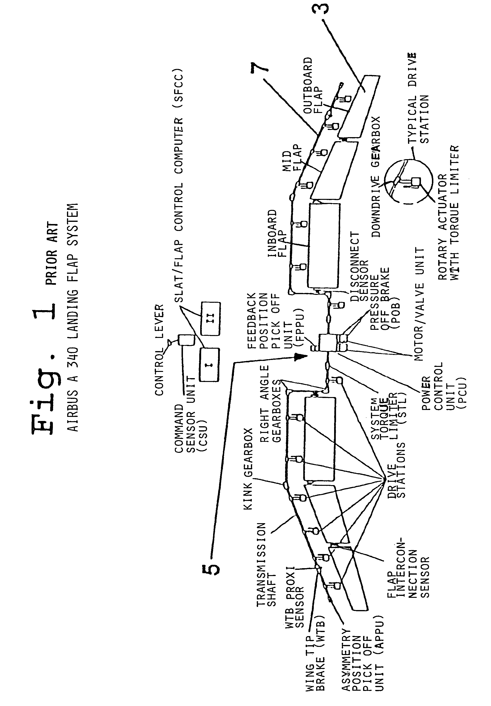
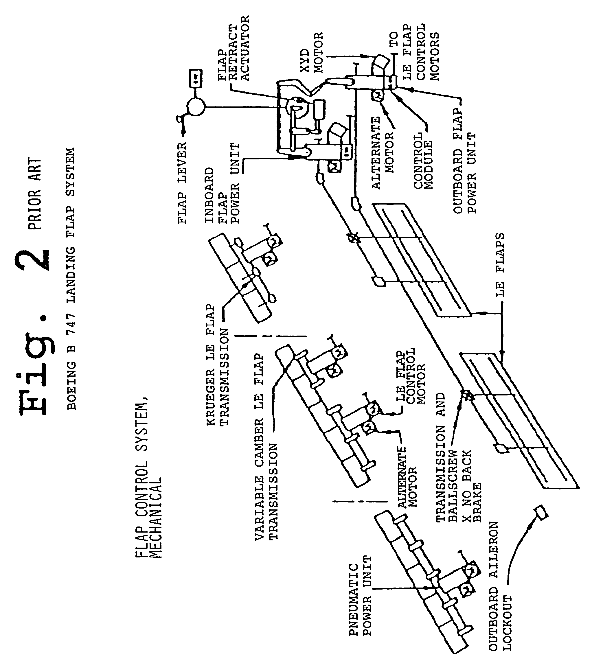
[0023]As discussed above, the landing flap systems of the Airbus A340 aircraft and of the Boeing B747 aircraft, as respectively schematically shown in FIGS. 1 and 2, as well as the flap systems of the DC9 and DC10 aircraft, form the general state of the art which is a starting point for the development of the present invention. Thus, these conventional flap systems are generally of interest to provide a better understanding of the invention, by particularly considering the differences between the conventional flap systems and the several example embodiments of the invention that will be discussed in detail hereinbelow.

[0024]As a general background, it must be considered that the future requirements in air traffic, for example relating to the increase in air traffic, the requirements of noise reduction, and the realization of a higher flexibility in the take-off and approach paths of airports, place ever higher demands on the functional flexibility and the availability in the event o...


PUM


Abstract

A drive station includes two drives connected via drive transmissions to one or more flaps or slats of a flap / slat group. The drives may be mechanically coupled to a rotational shaft, with a shaft brake arranged thereon. Guide transmissions are connected to the shaft and to respective flaps or slats of the flap / slat group. Alternatively, the two drives are not mechanically coupled, but are merely electrically or electronically synchronized. Each flap / slat group can be actuated individually and independently of the other groups by actuation commands provided by a central control unit connected to the drives and to a flight controller. Position sensors provide actual position feedback. Each flap / slat is driven by two transmissions, namely two drive transmissions, or two guide transmissions, or one drive transmission and one guide transmission. A redundant drive path is ensured if a component fails.

Description

CROSS-REFERENCE TO RELATED APPLICATIONS[0001]This application is related to U.S. application Ser. No. 10 / 868,175 filed Jun. 14, 2004 and U.S. application Ser. No. 11 / 021,723 filed Dec. 22, 2004.[0002]This application is based on and claims the priority under 35 U.S.C. §119 of German Patent Application 103 13 728.9 filed on Mar. 27, 2003, the entire disclosure of which is incorporated herein by reference.FIELD OF THE INVENTION[0003]The invention relates to a drive system for trailing edge flaps and / or leading edge slats on a fixed wing of an aircraft, including at least one flap / slat control unit and at least one drive or actuator for selectively actuating the extension and retraction or deflection movement of the slats and / or flaps.BACKGROUND INFORMATION[0004]Fixed wing aircraft are exemplified in civil aviation by modern passenger transport aircraft, such as the various aircraft models manufactured by Airbus and Boeing. Such fixed wing aircraft typically include slats movably arran...

Claims


Application Information

Patent Timeline
Patent Type & Authority Patents(United States)
IPC IPC(8): B64C13/38B64C13/00B64C3/00B64C13/50B64D45/00
CPCB64C13/503B64D45/0005B64D2045/001B64C13/505
Inventor RECKSIEK, MARTINRECHTER, HARALDBESING, WOLFGANG
Owner AIRBUS OPERATIONS GMBH
Why Eureka
Try Eureka