
Turbine fuel pump

Inactive Publication Date: 2006-05-23
HITACHI LTD
View PDF12 Cites 6 Cited by
  • Summary
  • Abstract
  • Description
  • Claims
  • Application Information

AI Technical Summary

Benefits of technology

[0009]Thus, in the related art, the respective vanes of the impeller tend to suffer from complicated and irregular cracks and breakage during the process for production of the fuel pump. In addition, if the shape of the respective vanes is out of design specification due to the cracks and breakage, there will occur problems such as deterioration in pump efficiency. To avoid these problems, specific facilities and control measures are required for preventing the vanes of the impeller from undergoing the occurrence of such cracks and breakage during the production process, resulting in increased production costs.
[0010]The present invention has been made in view of the above problems in the related arts. An object of the present invention is to provide a turbine fuel pump that can be free from occurrence of cracks or breakage in vanes of an impeller thereof, produced by a simple process due to facilitated handling thereof, and enhanced in pump efficiency.

Problems solved by technology

However, upon the molding and mechanical processing of the impeller as well as assembling thereof into a fuel pump, the impeller is exposed to various external forces.
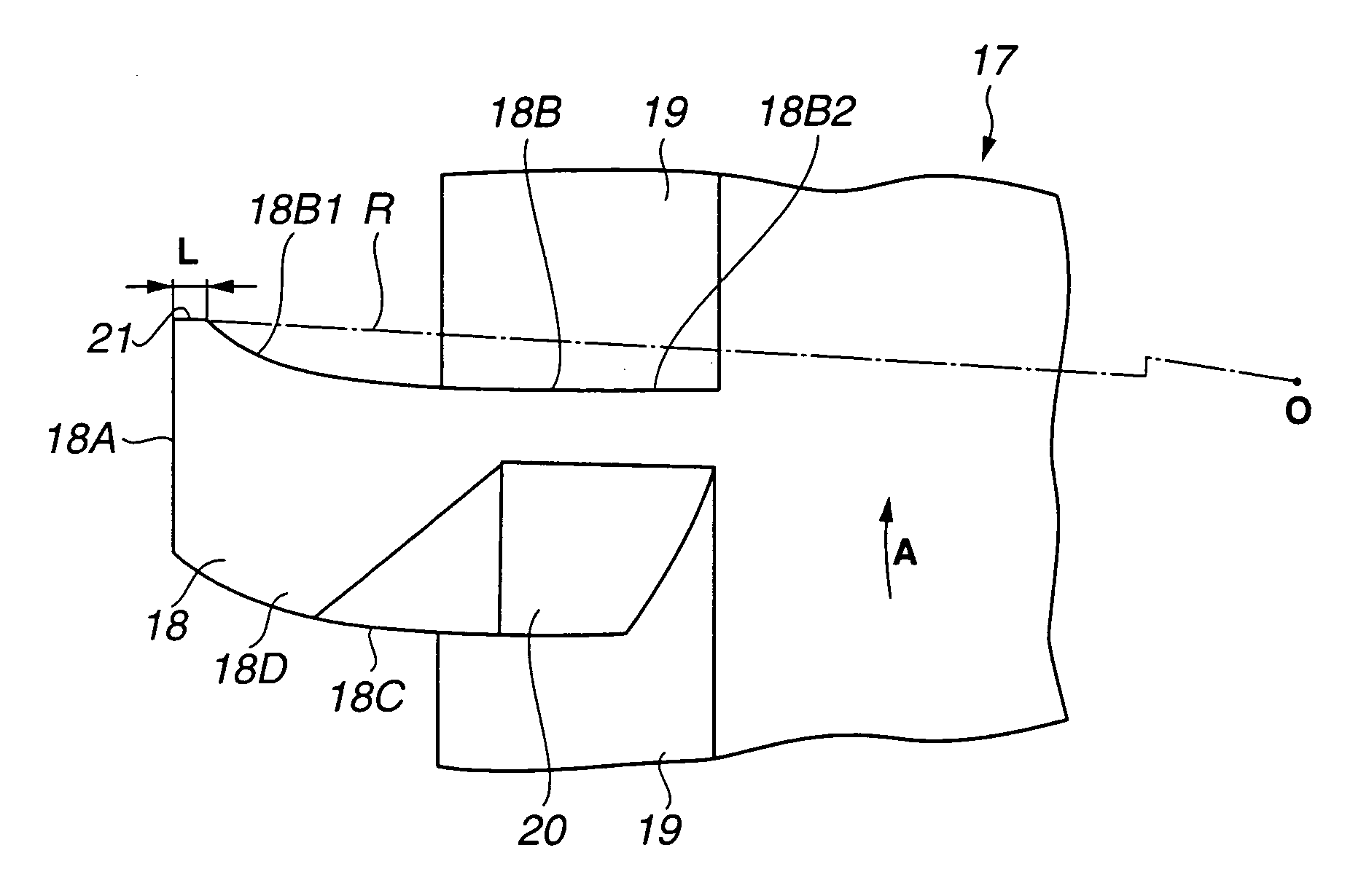
If the external forces are exerted onto the tip ends of the respective vanes of the impeller which have a pointed or acute-angled shape, there will occur such a risk that the tip ends of the vanes are broken.
Thus, in the related art, the respective vanes of the impeller tend to suffer from complicated and irregular cracks and breakage during the process for production of the fuel pump.
In addition, if the shape of the respective vanes is out of design specification due to the cracks and breakage, there will occur problems such as deterioration in pump efficiency.
To avoid these problems, specific facilities and control measures are required for preventing the vanes of the impeller from undergoing the occurrence of such cracks and breakage during the production process, resulting in increased production costs.

Method used


Image

  • Turbine fuel pump
  • Turbine fuel pump
  • Turbine fuel pump

Examples


Embodiment Construction

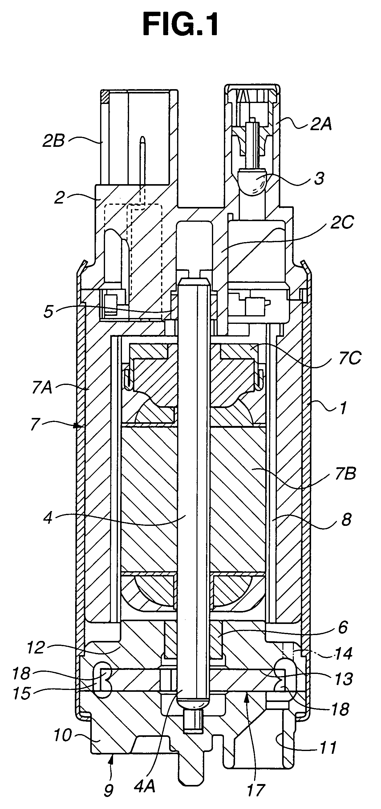
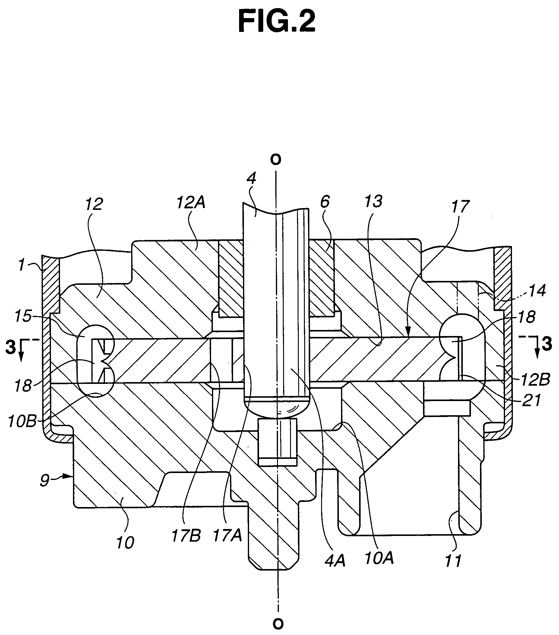
[0024]Referring to FIGS. 1 to 6, a turbine fuel pump according to a first embodiment of the present invention is explained in detail below. The fuel pump includes cylindrical casing 1 as an outer shell of the fuel pump. Opposite axial open ends of casing 1 are respectively closed by discharge cover 2 and pump housing 9 as described in detail later.

[0025]Discharge cover 2 is of a bottom-closed cylindrical shape, and includes discharge port 2A and connector portion 2B both projecting outwardly from discharge cover 2, as well as bearing sleeve 2C formed at a center thereof so as to extend toward an inside of casing 1.

[0026]Check valve 3 for retention of residual pressure is disposed within discharge port 2A. Check valve 3 is opened upon rotation of electric motor 7 as described later to discharge fuel flowing through casing 1 from discharge port 2A toward an external fuel conduit (not shown), etc. Check valve 3 is closed upon disenergization of electric motor 7 for preventing the fuel ...


PUM


Abstract

A turbine fuel pump including a cylindrical casing, an electric motor accommodated in the casing, a pump housing mounted into the casing, and an impeller disposed within the pump housing and driven around an axis in a rotational direction by the electric motor. The impeller includes a plurality of vanes each formed into a generally rectangular plate including a tip end face that extends circumferentially to define an outer peripheral surface of the impeller, and front and rear faces respectively located on forward and rearward sides in the rotational direction of the impeller. The front face is curved such that a tip end portion thereof is positioned forwardly in the rotational direction of the impeller relative to a root portion thereof. A chamfer portion is disposed between the tip end face and a tip end portion of the front face.

Description

BACKGROUND OF THE INVENTION[0001]The present invention relates to a fuel pump of a turbine type which is suitably adapted for feeding fuel, for example, to an engine of automobiles.[0002]In general, vehicles such as automobiles are provided with a fuel pump for feeding fuel to an engine thereof. As the fuel pump, there are known fuel pumps of a turbine type in which a disk-shaped impeller is rotatively driven to feed the fuel under pressure.[0003]Japanese Patent Application First Publication No. 6-229388 discloses a fuel pump including a cylindrical casing, an electric motor as a power source for the fuel pump and a rotating shaft coupled to an output side of the electric motor which are accommodated in the casing.[0004]A pump housing is disposed at one end portion of the casing in which a tip end portion of the rotating shaft is located. A suction port, a discharge port and an annular fuel path connected to the suction and discharge ports are defined within the pump housing. An imp...

Claims


Application Information

Patent Timeline
IPC IPC(8): F04D5/00F02M37/10F04D29/18
CPCF04D29/188
Inventor IIJIMA, MASAAKIMOTOJIMA, JUNICHI
Owner HITACHI LTD
Learn More