
Particle beam irradiation system and method of adjusting irradiation field forming apparatus

a technology of irradiation field and particle beam, which is applied in the direction of x-ray/gamma-ray/particle-irradiation therapy, therapy, nuclear engineering, etc., can solve the problems of difficult to keep high uniformity of dose distribution in a direction perpendicular to the advance direction of ion beam, and reduce penumbra. , the effect of increasing the beam size and increasing the size of the apparatus

Active Publication Date: 2006-05-23
HITACHI LTD
View PDF20 Cites 192 Cited by
  • Summary
  • Abstract
  • Description
  • Claims
  • Application Information

AI Technical Summary

Benefits of technology

[0009]When the SOBP device is arranged on the downstream side in the direction of advance of the ion beam, the effective beam distance up to the irradiation position (i.e., the diseased part) reduces and a blur (penumbra) in the irradiation dose distribution spreading beyond the irradiation target increases correspondingly. Further, the beam size increases and hence the apparatus size also increases. On the other hand, when the SOBP device is arranged on the upstream side, the penumbra can be reduced, but uniformity of the dose distribution in a direction perpendicular to the direction of advance of the ion beam is difficult to keep high because of an increase of influences upon, e.g., a change in incident energy of the ion beam and a change in thickness of an ion beam passage area within a range adjusting device that is arranged on the downstream side to vary the range of the ion beam.
[0010]Accordingly, it is an object of the present invention to provide a particle beam irradiation system and a method of adjusting an irradiation field forming apparatus, which can produce a more uniform dose distribution in a direction perpendicular to the direction of advance of the ion beam.
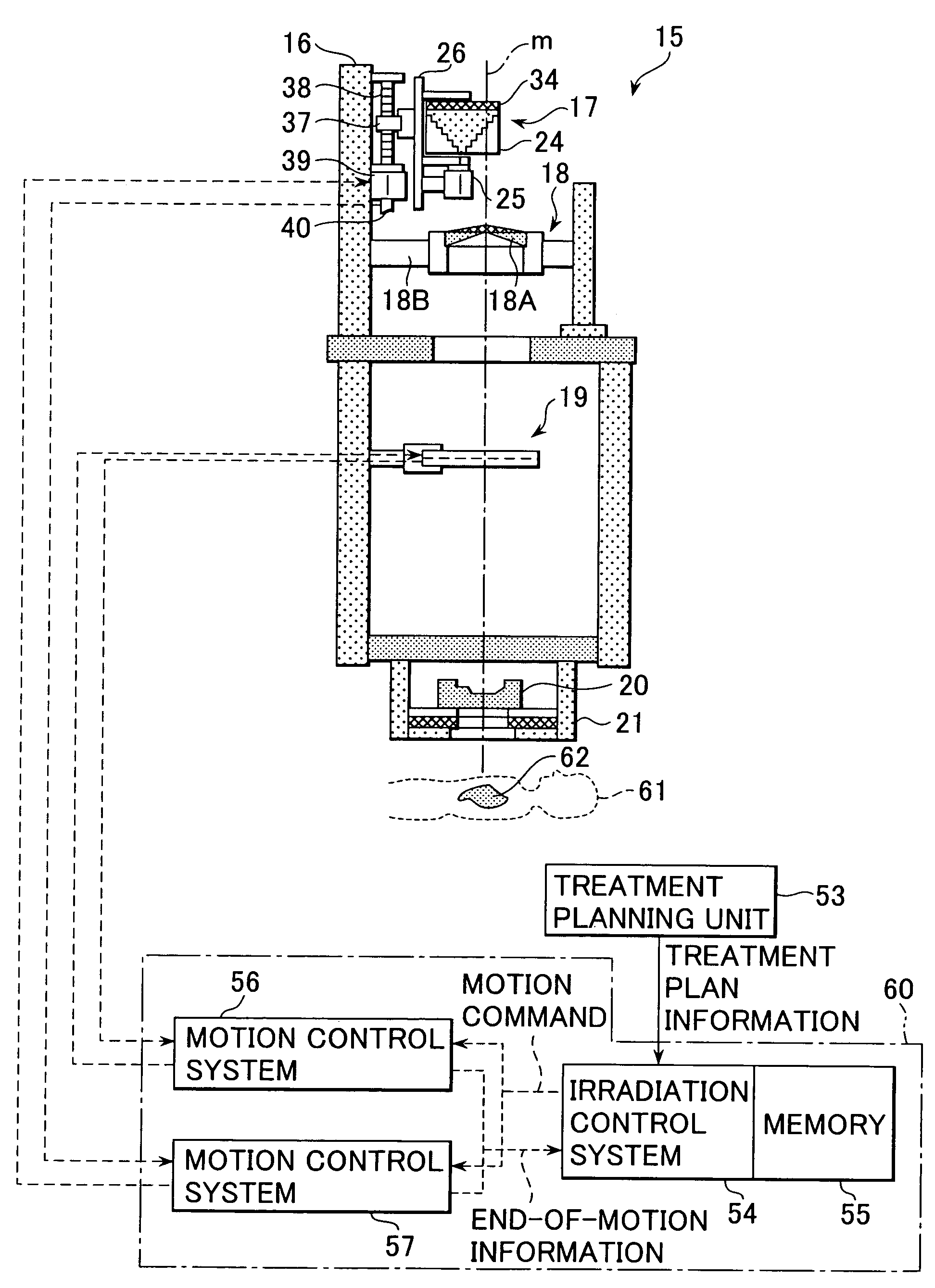
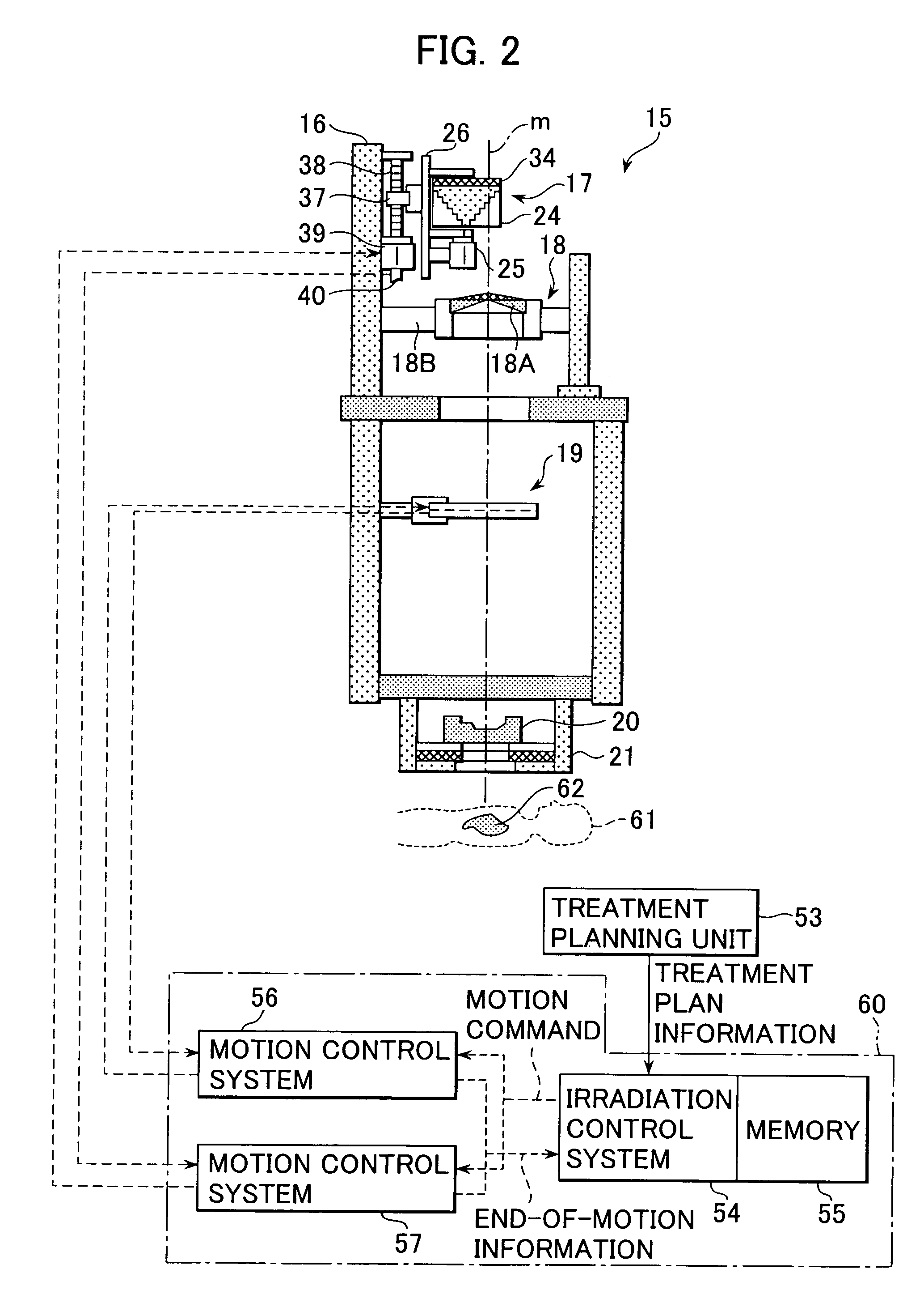
[0011]To achieve the above object, the present invention is featured in that a scattering compensator for compensating differences in scattering intensity of a charged particle beam in a Bragg peak spreading-out device is provided on the Bragg peak spreading-out device, and the Bragg peak spreading-out device and the scattering compensator are mounted in an irradiation field forming apparatus movably in a direction of advance of the charged particle beam. In other words, by providing the scattering compensator on the Bragg peak spreading-out device, the Bragg peak spreading-out device and the scattering compensator can be arranged on the upstream side in the direction of beam advance, and a penumbra in dose distribution can be reduced with such an arrangement. Further, since the Bragg peak spreading-out device and the scattering compensator are movable in the direction of beam advance, a dose distribution of the charged particle beam at an irradiation target position in a direction perpendicular to the direction of beam advance can be made more uniform by optimally adjusting the position of the Bragg peak spreading-out device and the scattering compensator.
[0012]Thus, according to the present invention, it is possible to reduce the penumbra, and to produce a more uniform dose distribution at the irradiation target position of the charged particle beam in the direction perpendicular to the direction of beam advance.

Problems solved by technology

However, the above-described related art has problems given below.
On the other hand, when the SOBP device is arranged on the upstream side, the penumbra can be reduced, but uniformity of the dose distribution in a direction perpendicular to the direction of advance of the ion beam is difficult to keep high because of an increase of influences upon, e.g., a change in incident energy of the ion beam and a change in thickness of an ion beam passage area within a range adjusting device that is arranged on the downstream side to vary the range of the ion beam.

Method used


Image

  • Particle beam irradiation system and method of adjusting irradiation field forming apparatus
  • Particle beam irradiation system and method of adjusting irradiation field forming apparatus
  • Particle beam irradiation system and method of adjusting irradiation field forming apparatus

Examples


second embodiment

[0044]An particle therapy system according to another preferable embodiment, i.e., a second embodiment, of the present invention will be described below. The particle therapy system of this embodiment differs from the particle therapy system 1, shown in FIG. 1, in that the irradiation field forming apparatus 15 and the control system 60 are replaced respectively with the irradiation field forming apparatus 15A and the control system 60A shown in FIG. 8. In the irradiation field forming apparatus 15A of this embodiment, the scatterer device 18 and the range adjusting device 19 are movable in the direction of beam advance in addition to the RMW device 17. More specifically, a support member 18B of the scatterer device 18 is mounted to a support member 66 having a screwed hole (not shown) in mesh with a ball screw 65 and also to a support member 67 having through hole (not shown). The ball screw 65 has an upper end rotatably mounted to the casing 16 and a lower end coupled to an AC ser...


PUM


Abstract

A particle therapy system, as one example of a particle beam irradiation system, comprises a charged particle beam generator and an irradiation field forming apparatus. An ion beam from the charged particle beam generator is irradiated to a diseased part in the body of a patient through the irradiation field forming apparatus. A scattering compensator and a range modulation wheel (RMW) are disposed on the upstream side in a direction of beam advance and are movable along a beam axis. The movement of the scattering compensator and the RMW adjusts a size of the ion beam entering a scatterer device, whereby a change in scattering intensity of the ion beam in the scatterer device is adjusted. As a result, a penumbra in dose distribution is reduced and a more uniform dose distribution in a direction perpendicular to the direction of beam advance is obtained in the diseased part.

Description

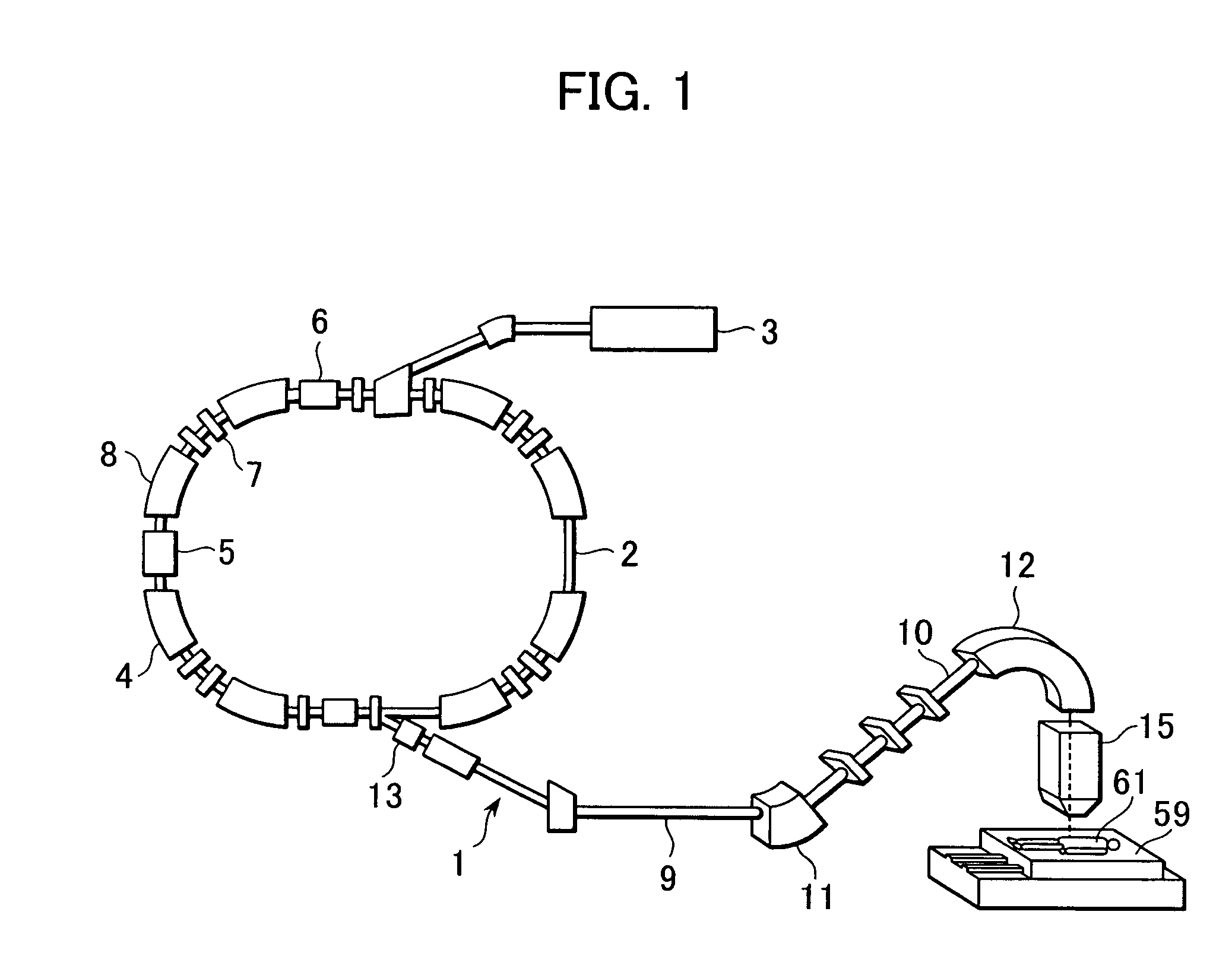
BACKGROUND OF THE INVENTION[0001]1. Field of the Invention[0002]The present invention relates to a particle beam irradiation system and a method of adjusting an irradiation field forming apparatus. More particularly, the present invention relates to a particle beam irradiation system suitable for use as a particle therapy system for irradiating a charged particle beam, such as a proton or carbon ion beam, to a diseased part (cancer) for treatment, a material irradiation system for irradiating a charged particle beam to materials, a food irradiation system for irradiating a charged particle beam to foods, and a radio isotope producing system utilizing a charged particle beam.[0003]2. Description of the Related Art[0004]A known particle therapy system comprises a charged particle beam generator, a beam transport system, and a rotating irradiation apparatus. The charged particle beam generator includes a synchrotron (or a cyclotron) as an accelerator. A charged particle beam (hereinaft...

Claims


Application Information

Patent Timeline
Patent Type & Authority Patents(United States)
IPC IPC(8): H05H9/00G21K3/00A23L5/30A61N1/44A61N5/00A61N5/10G21K1/10G21K5/04G21K5/10
CPCG21K1/10A61N1/44A61N2005/1095A61N2005/1087
Inventor YANAGISAWA, MASAKIAKIYAMA, HIROSHIMATSUDA, KOJIFUJIMAKI, HISATAKA
Owner HITACHI LTD
Learn More