Dynamoelectric machine stator and method for mounting prewound coils thereunto

a technology of dynamoelectric machines and stator slots, which is applied in the direction of windings, windings, windings insulation materials, etc., can solve problems such as short circuits, and achieve the effect of reducing the need for deforming the corresponding conductor section and facilitating insertion

Inactive Publication Date: 2006-05-23
TM4 INC
View PDF8 Cites 23 Cited by
  • Summary
  • Abstract
  • Description
  • Claims
  • Application Information

AI Technical Summary

Benefits of technology

[0013]Advantages of the present invention include that the proposed dynamoelectric machine stator is provided with slots allowing for insertion thereinto of pre-wound coils or windings with reduced or absent need for distorting or otherwise deforming the coils or windings. Accordingly, the stator slots of the proposed dynamoelectric machine stator inherently reduce the risks of damaging the insulation of the coils and, hence, reduce the risks of potentially causing short circuits.
[0015]The proposed method for mounting the pre-wound coils into the stator slots of the dynamoelectric machine stator, in accordance with the present invention, enables the manufacture of a dynamoelectric machine stator that is economically feasible.
[0018]the slot first and second sections communicating with each other and being in a circumferentially offset relationship relative to each other, and being positioned, configured and sized to facilitate insertion therein of a corresponding conductor section of the stator winding with reduced needs for deforming the corresponding conductor section.
[0021]In accordance with still a further aspect of the present invention, there is provided yet still a dynamoelectric machine comprising: a stator having a core body made of ferromagnetic material, the core body defining a pair of axially opposed core end surfaces and a substantially cylindrical core main peripheral surface extending between the core end surfaces; a plurality of substantially axially extending stator slots circumferentially spaced in the core body, the stator slots defining intervening teeth projecting substantially radially towards the core main peripheral surface; each of the stator slots extending radially from a corresponding slot base to the core main peripheral surface; wherein each of the stator slots defines a slot first section extending radially from the slot base to a slot intermediate radial position located intermediate the slot base and the core main peripheral surface; a slot second section extending radially from substantially adjacent the slot intermediate radial position towards the core main peripheral surface; the slot first and second sections communicating with each other and being in a circumferentially offset relationship relative to each other; a stator winding embedded in the stator slots; a rotor made of ferromagnetic material positioned so as to define a substantially cylindrical stator-to-rotor gap between the core main peripheral surface and the rotor, the rotor being supported for rotational movement relative to the stator, the rotor including conductive means for interacting with a magnetic field produced in the stator-to-rotor gap when the stator winding is energized whereby the slot first and second sections are positioned, configured and sized to facilitate insertion therein of a corresponding conductor section of the stator winding with reduced needs for deforming the corresponding conductor section.

Problems solved by technology

After a coil is wound with such conductors, it is thereafter covered with coil insulation that binds the conductors together and severely restricts any relative motion therebetween thereafter.
A common problem associated with the manufacture of such “formed wound machines” is related to the difficulty of inserting the pre-formed coils or windings in the stator slots without distorting or deforming the coils so as to reduce the risks of damaging the insulation thereof and potentially causing short circuits or the like.

Method used


Image

  • Dynamoelectric machine stator and method for mounting prewound coils thereunto
  • Dynamoelectric machine stator and method for mounting prewound coils thereunto
  • Dynamoelectric machine stator and method for mounting prewound coils thereunto

Examples


Embodiment Construction

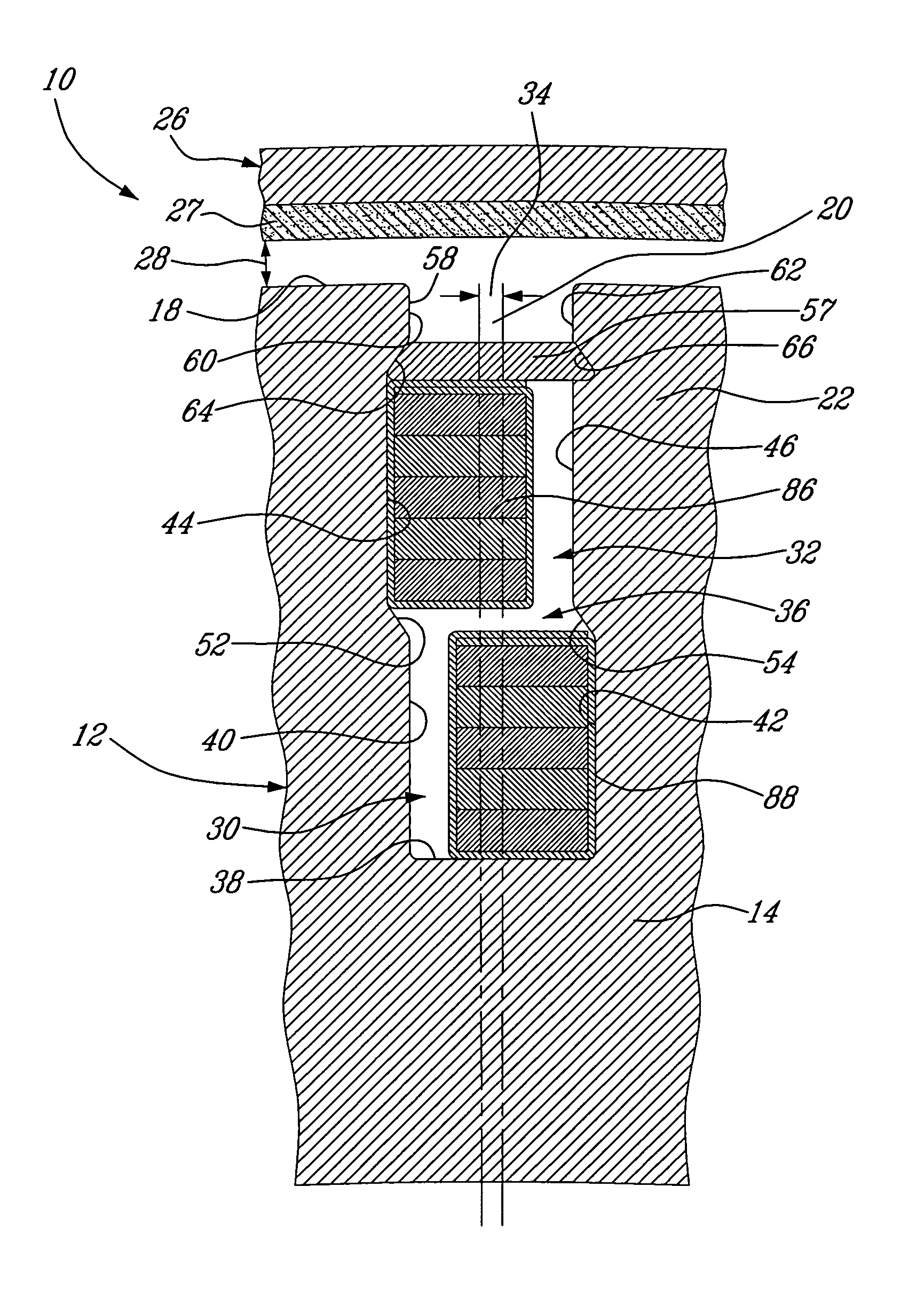
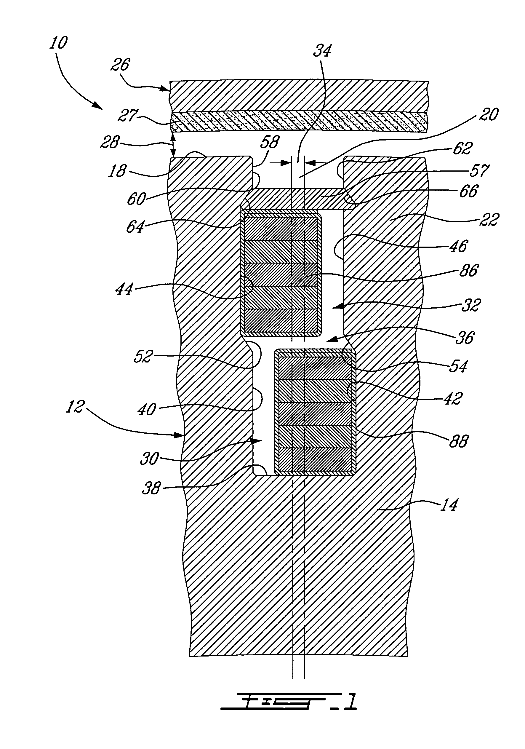
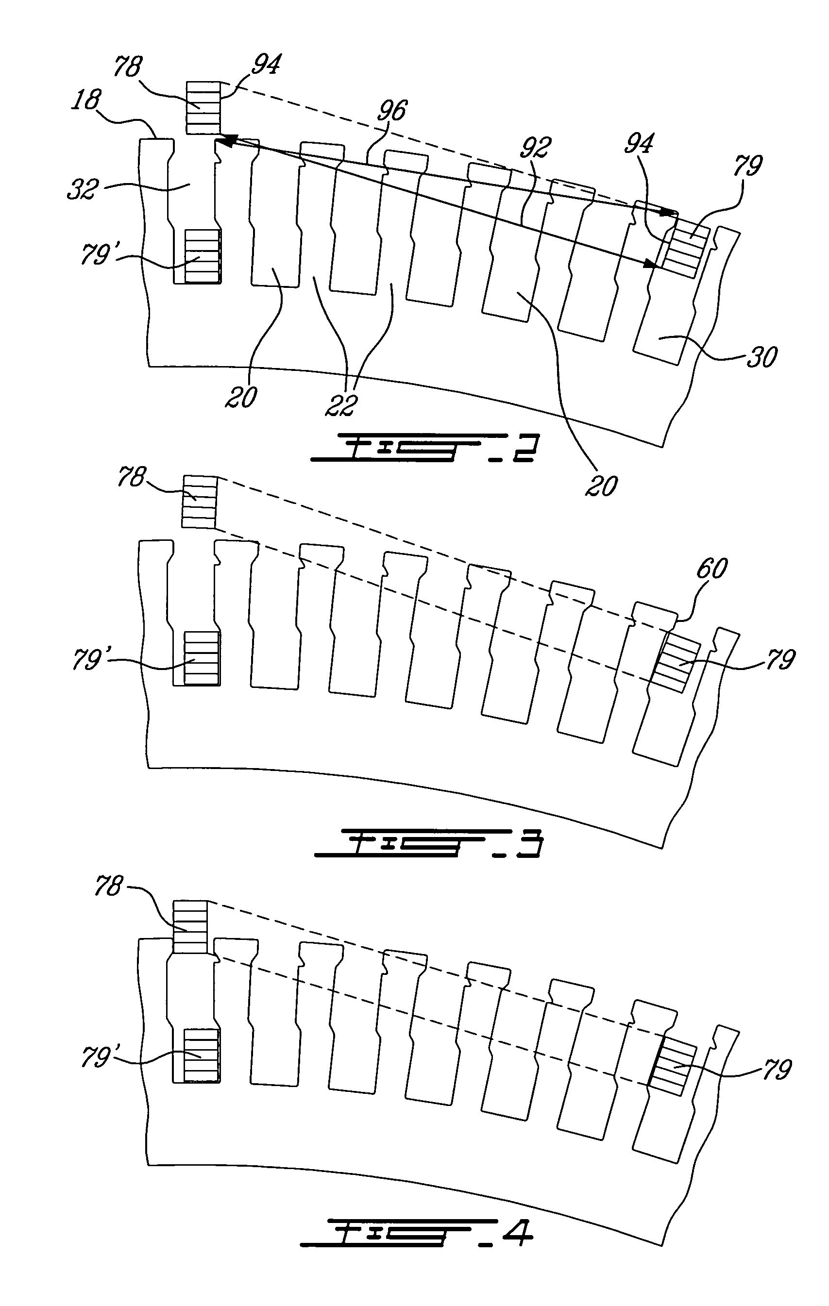
[0042]Referring to FIG. 14, there is schematically shown part of a dynamoelectric machine generally indicated by the reference numeral 10. The dynamoelectric machine 10 has a stator core generally indicated by the reference numeral 12 in accordance with an embodiment of the present invention. The machine 10 also includes a rotor 26.

[0043]Although the present invention is hereinafter disclosed in the context of an electric machine having a radially inwardly located stator and a radially outwardly positioned rotor, it should be understood that the inventive concepts of present invention could be applied to other contexts such as to the rotor portion of the machines instead of the stator portion of the machine and even to other types of dynamoelectric machines having other types of configurations without departing from the scope of the present invention.

[0044]In the embodiments shown throughout the figures, the stator core 12 has a core body 14 typically made of ferro-magnetic material...


PUM

PropertyMeasurementUnit
circumferential offsetting distanceaaaaaaaaaa
segment-to-wall angleaaaaaaaaaa
slot depthaaaaaaaaaa

Abstract

A dynamoelectric machine stator core for receiving a pre-formed stator winding includes a core body defining a cylindrical core main peripheral surface. A plurality of axially extending stator slots are circumferentially spaced in the core body. Each of the stator slots defines a slot first section extending radially from the slot base to a slot intermediate radial position and a slot second section extending radially from the slot intermediate radial position towards the core main peripheral surface. The slot first and second sections communicate with each other and are circumferentially offset relative to each other. The slot first and second sections are positioned, configured and sized to facilitate insertion therein of a corresponding conductor section of the stator winding with reduced needs for deforming the latter.

Description

FIELD OF THE INVENTION[0001]The present invention relates to the general field of dynamoelectric machines and is particularly concerned with a stator slot configuration and a method for mounting pre-wound coils in stator slots having such stator slot configuration.BACKGROUND OF THE INVENTION[0002]Dynamoelectric machines such as electric motors, alternators and the like are typically constructed with an annular stator within which a rotating field is rotatably mounted. The stator construction typically includes an annular magnetic core having circumferentially distributed and axially extending stator slots. The stator winding consists of coils spanning the distance of a pole pitch and interconnected together to form groups in accordance with the phase connection.[0003]In some instances, it is advantageous for the stator to be internally positioned relative to an external rotor. For example, U.S. Pat. No. 5,355,039 entitled “ELECTRICLALY MOTORIZED WHEEL ASSEMBLY” issued on Oct. 7, 199...

Claims


Application Information

Patent Timeline
Patent Type & Authority Patents(United States)
IPC IPC(8): H02K3/30H02K3/32H02K3/34H02K1/16H02K15/06
CPCH02K1/165H02K15/06Y10T29/49009H02K3/34H02K1/16H02K3/28
Inventor BLOUIN, PIERREPOULIN, STEPHANE
Owner TM4 INC
Why Eureka
Try Eureka