Converter circuit with short-circuit current protection

a converter circuit and short-circuit current technology, applied in the direction of motor/generator/converter stopper, electric/dynamo-electric converter starter, dynamo-electric converter control, etc., can solve the problems of large space occupation of two fuses to be provided for the dc voltage circuit subsystem, high electrical and thermal load on these components with respect to power loss, etc., to reduce the total parasitic inductance ,

Active Publication Date: 2006-05-23
ABB (SCHWEIZ) AG
View PDF7 Cites 8 Cited by
  • Summary
  • Abstract
  • Description
  • Claims
  • Application Information

AI Technical Summary

Benefits of technology

[0005]The converter circuit with short-circuit current protection according to the invention has a DC voltage circuit which is formed by a DC voltage circuit subsystem, the DC voltage circuit subsystem having a first energy store and a second energy store, which is connected in series with the first energy store, and a fuse. Furthermore, the converter circuit has at least one pair of branches provided for each phase and connected in parallel with the DC voltage circuit, each pair of branches having power semiconductor switches. According to the invention, the fuse forms the connection between the first energy store and the second energy store. Advantageously, this makes it possible to achieve a DC voltage circuit, and thus a converter circuit with short-circuit current protection, with low inductance, since, in comparison with a converter circuit with short-circuit current protection according to the prior art, a fuse can be dispensed with, and thus the total parasitic inductance of the converter circuit can be reduced. Furthermore, the advantageously reduced total parasitic inductance results in any electrical oscillation between the total parasitic inductance and the energy stores of the DC voltage circuit, brought about by a power semiconductor switch of a pair of branches of the converter circuit being switched, in particular being switched off, and having an only very small amplitude, in particular current amplitude. The electrical and thermal load on the components of the converter circuit can thus advantageously be reduced.
[0006]Furthermore, the assembly and design of the converter circuit with short-circuit current protection according to the invention are, owing to the use of only one fuse for the DC voltage circuit subsystem, very simple and it requires few components, which means that considerable cost savings can be made. In addition, the converter circuit according to the invention only requires a minimum amount of space and can thus advantageously have a compact design. The converter circuit according to the invention is advantageously suitable for applications with a single-phase supply and for applications having a large energy storage capacity.

Problems solved by technology

One problem with a converter circuit with short-circuit current protection according to “Determination of added inductance by fuses in DC-link inverter applications, Drive & Control Mar. 13–15, 2001, London” is the fact that the two fuses connected in series with the capacitors and the connection of the two capacitors result in the DC voltage circuit, and thus the converter circuit with short-circuit current protection, being highly inductive, since the parasitic inductances of the two fuses and of the connection of the two capacitors are totaled.
This leads to higher electrical and thermal loads on these components with respect to power loss.
Furthermore, the design of the DC voltage circuit subsystem, owing to the two fuses, is complex in terms of assembly and requires a large number of components which results in considerable costs.
In addition, the two fuses to be provided for the DC voltage circuit subsystem occupy a large amount of space.
A more compact design for a converter circuit with short-circuit current protection, as is required, for example, for traction applications in electric railroads, is thus not possible or only possible to a very limited extent.

Method used


Image

  • Converter circuit with short-circuit current protection
  • Converter circuit with short-circuit current protection
  • Converter circuit with short-circuit current protection

Examples


first embodiment

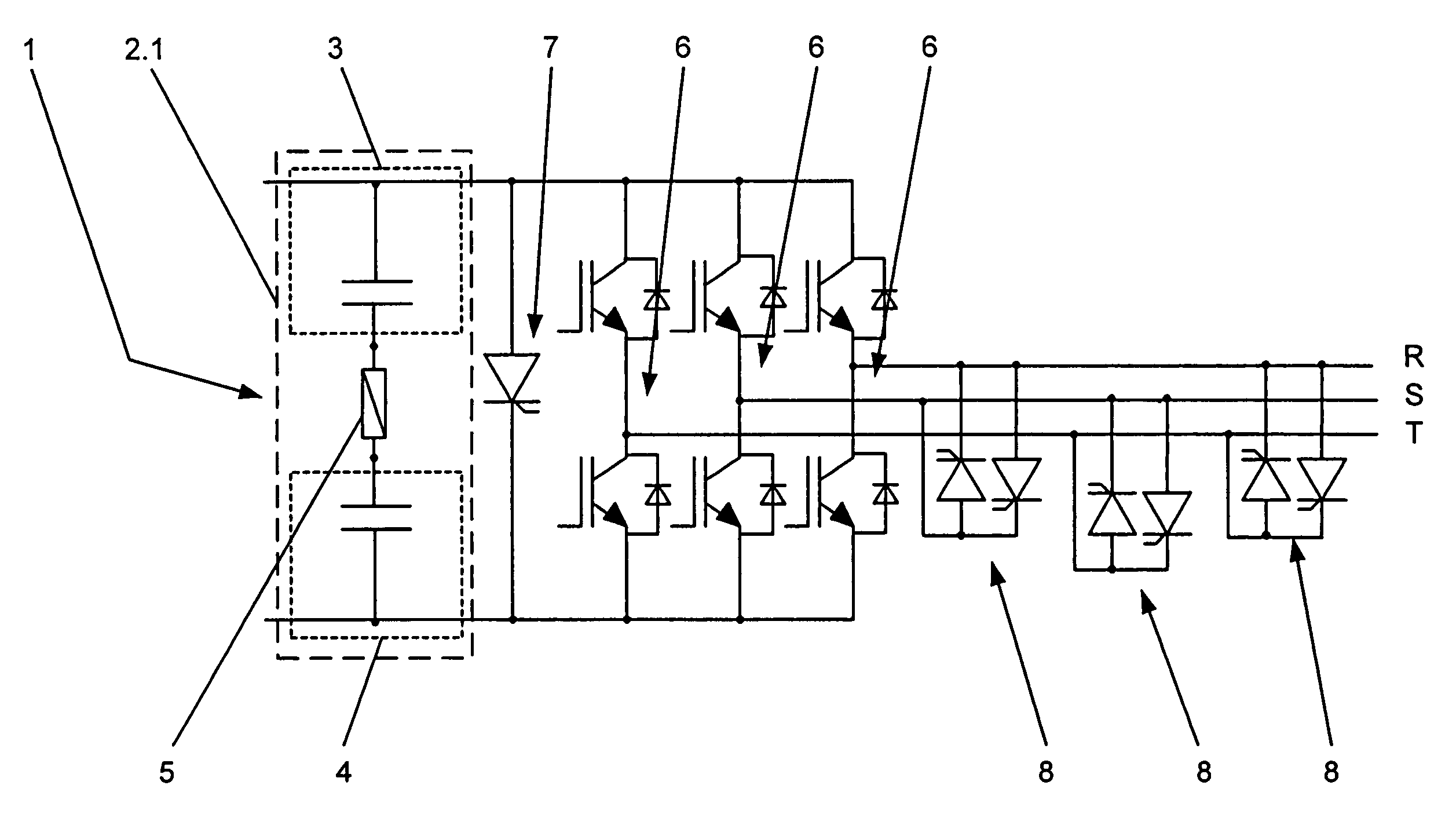
[0009]FIG. 1 shows a converter circuit with short-circuit current protection according to the invention,

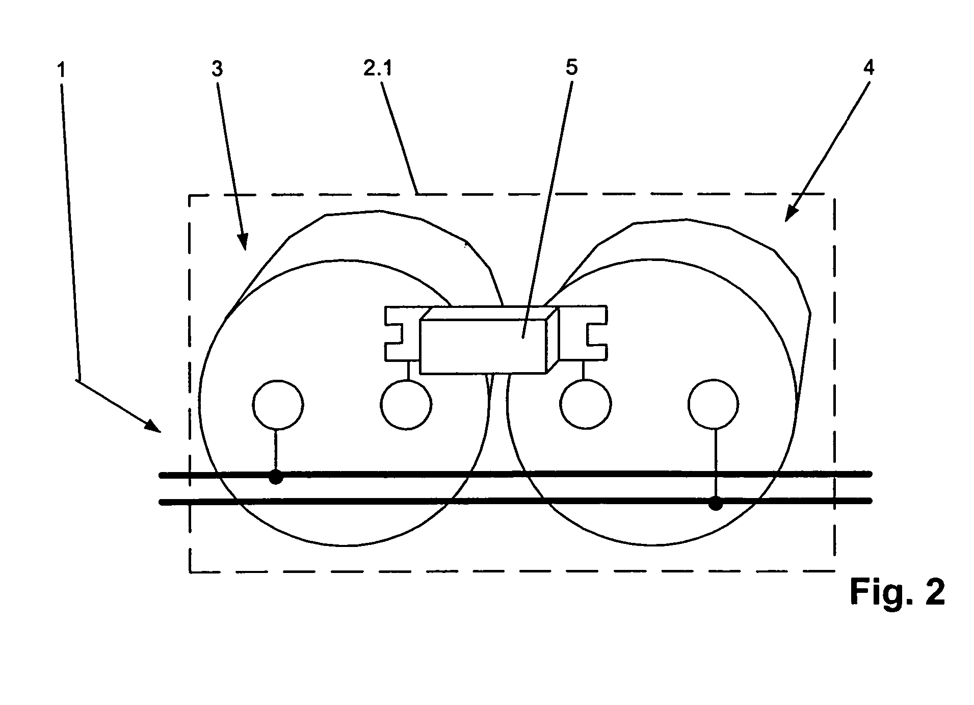
[0010]FIG. 2 shows a detail of the first embodiment of the converter circuit with short-circuit current protection according to the invention shown in FIG. 1,

second embodiment

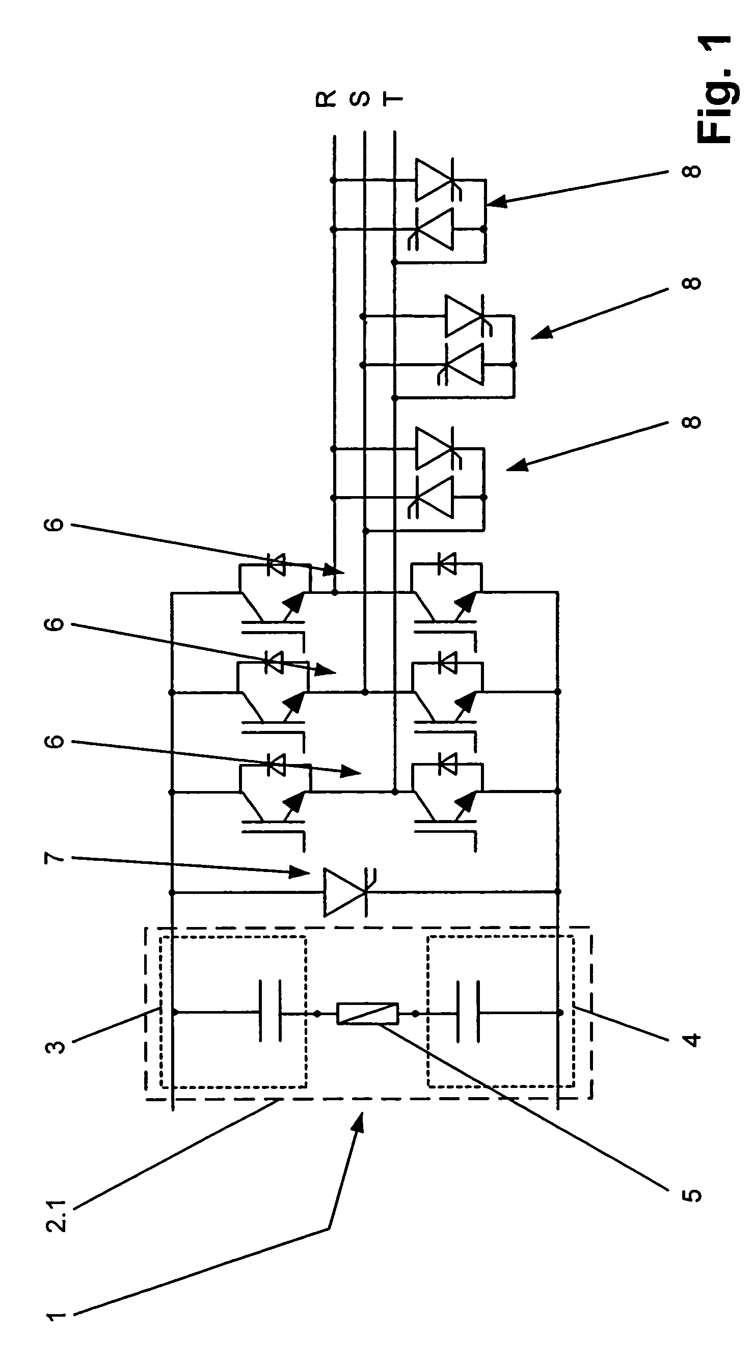
[0011]FIG. 3 shows a converter circuit with short-circuit current protection according to the invention,

[0012]FIG. 4 shows a detail of the second embodiment of the converter circuit with short-circuit current protection according to the invention shown in FIG. 3, and

third embodiment

[0013]FIG. 5 shows a converter circuit with short-circuit current protection according to the invention.

[0014]The reference numerals used in the drawing and their meanings are listed in summary in the list of reference numerals. In principle, identical parts in the figures are provided with identical reference numerals. The described embodiments represent by way of example the inventive subject matter and do not have a limiting effect.

Ways of Implementing the Invention

[0015]FIG. 1 shows a first embodiment of a converter circuit with short-circuit current protection according to the invention. Furthermore, FIG. 2 shows a detail of the first embodiment of the converter circuit with short-circuit current protection according to the invention shown, in FIG. 1. According to FIG. 1, the converter circuit according to the invention has a DC voltage circuit 1 which is formed by a DC voltage circuit subsystem 2.1, the DC voltage circuit subsystem 2.1 having a first energy store 3 and a secon...


PUM


Abstract

A converter circuit with short-circuit current protection having a DC voltage circuit (1) is proposed, which DC voltage circuit (1) is formed by a DC voltage circuit subsystem (2.1), the DC voltage circuit subsystem (2.1) having a first energy store (3) and a second energy store (4), which is connected in series with the first energy store (3), and a fuse (5). Furthermore, the converter circuit has at least one pair of branches (6) provided for each phase (R, S, T) and connected in parallel with the DC voltage circuit (1), each pair of branches (6) having power semiconductor switches. In order to achieve a low-inductance converter circuit, the fuse (5) forms the connection between the first energy store (3) and the second energy store (4).

Description

TECHNICAL BACKGROUND[0001]The invention relates to the field of power electronics. It is based on a converter circuit with short-circuit current protection according to the preamble of the independent claim.PRIOR ART[0002]Converter circuits are used today in a wealth of power electronics applications, for example in drive technology for railroad applications or in solid-state conversion devices. Such a converter circuit is usually protected against the occurrence of a short-circuit current to prevent the converter circuit from being damaged or destroyed. Such a converter circuit with short-circuit current protection is mentioned, for example, in “Determination of added inductance by fuses in DC-link inverter applications, Drive & Control Mar. 13–15, Mar. 2001 London”. In this case the converter circuit has a DC voltage circuit which is formed by a DC voltage circuit subsystem, the DC voltage circuit subsystem having a first energy store. The DC voltage circuit subsystem also has a s...

Claims


Application Information

Patent Timeline
Patent Type & Authority Patents(United States)
IPC IPC(8): H02P27/04H02M1/12H02H3/08H02M1/00H02M7/00
CPCH02M7/003H02M1/32
Inventor KNAPP, GEROLDMAURON, PASCALSTEMMLER, CHRISTOPH
Owner ABB (SCHWEIZ) AG
Why Eureka
Try Eureka