Heater-equipped pusher, electronic component handling apparatus, and temperature control method for electronic component

a technology of electronic components and pushers, which is applied in the direction of individual semiconductor device testing, semiconductor/solid-state device testing/measurement, instruments, etc., can solve the problems of poor yield, inability to perform accurate test on ic devices, and judge good products as defective products, so as to prevent excessive temperature rises in electronic components to be tested

Active Publication Date: 2006-05-23
ADVANTEST CORP
View PDF18 Cites 29 Cited by
  • Summary
  • Abstract
  • Description
  • Claims
  • Application Information

AI Technical Summary

Benefits of technology

[0012]In the present invention, when the temperature of the pusher rises above a predetermined set temperature, the heat absorbing and radiating body provided on the pusher main body absorbs and radiates the heat (heat absorption and radiation) in the pusher, and thus the temperature of the electronic component to be tested which is pushed by the pusher can be prevented from rising excessively above the set temperature. When the contact portion of the test head is lower than the predetermined set temperature, heat is generated in the heater such that the electronic component to be tested contacting the heater is heated and thus nears the set temperature. When the electronic component to be tested reaches a higher temperature than the set temperature due to self-induced heat generation, the heat in the electronic compon

Problems solved by technology

When the temperature of an IC device diverges so greatly from the set temperature, it is impossible to perform an accurate test on the IC device.
For example, if a test is performed on an IC device at a much lower temperature than the set temperature, defective products may be judged to be good products, and if a test is performed on an IC device at a much higher temperature than the set temperature, good products are judged to be defective products such that yield deteriorates.
In

Method used


Image

  • Heater-equipped pusher, electronic component handling apparatus, and temperature control method for electronic component
  • Heater-equipped pusher, electronic component handling apparatus, and temperature control method for electronic component
  • Heater-equipped pusher, electronic component handling apparatus, and temperature control method for electronic component

Examples


Embodiment Construction

[0027]An embodiment of the present invention will be described herein below on the basis of the drawings.

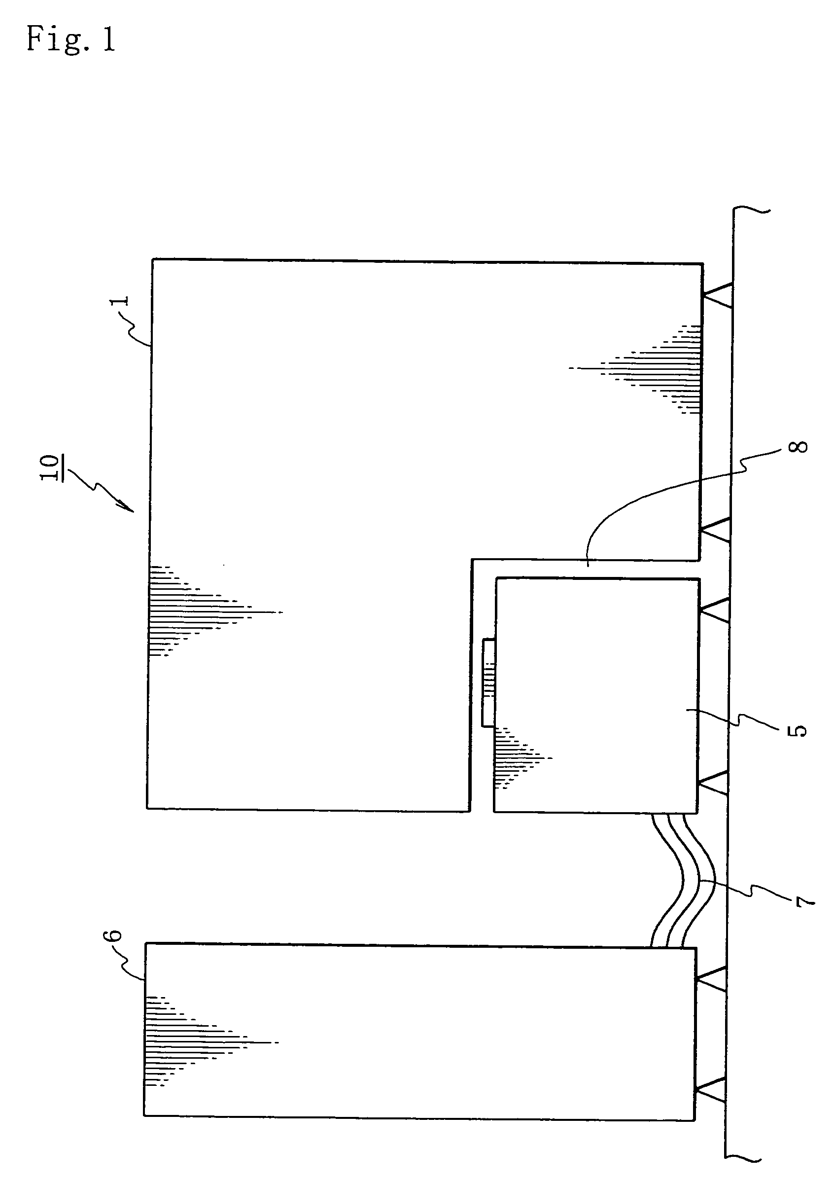
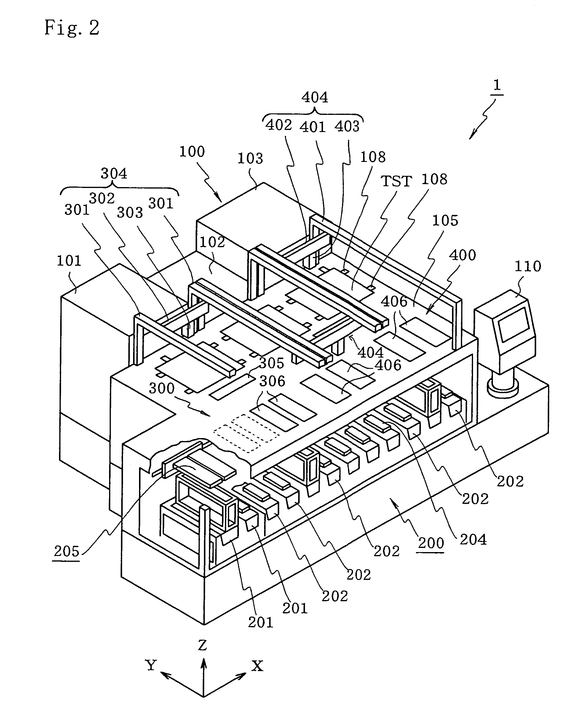
[0028]First, the overall constitution of an IC device testing apparatus comprising a handler according to an embodiment of the present invention will be described. As shown in FIG. 1, an IC device testing apparatus 10 comprises a handler 1, a test head 5, and a main testing apparatus 6. The handler 1 executes an operation to successively transport IC devices (an example of an electronic component) subject to testing to a socket provided on the test head 5, classify the tested IC devices according to the test results, and store the tested IC devices in predetermined trays.

[0029]The socket provided on the test head 5 is electrically connected to the main testing apparatus 6 through a cable 7 so as to connect the IC devices which are removably installed in the socket to the main testing apparatus 6 through the cable 7. The IC devices are tested by means of an electric testing signal...


PUM


Abstract

A pusher is constituted by a pusher main body, which is capable of direct contact with an electronic component to be tested, a heat absorbing and radiating body provided on the pusher main body, a heater provided on the pusher main body to enable direct or indirect contact with the electronic component to be tested, and a thermal insulating material provided between the pusher main body and the heater. According to such a pusher, temperature control of an electronic component can be performed such that the electronic component nears a target set temperature for testing.

Description

TECHNICAL FIELD[0001]The present invention relates to a pusher which is capable of performing temperature control on an electronic component such as an IC device in an apparatus for testing electronic components, an electronic component handling apparatus comprising such a pusher, and a temperature control method for an electronic component.BACKGROUND ART[0002]In a manufacturing process for an electronic component such as an IC device, a testing apparatus is required for testing the electronic component which is finally manufactured. An apparatus for testing a plurality of IC devices at one time under higher temperature conditions than normal temperature (thermal stress conditions) is known as one type of such a testing apparatus.[0003]In this testing apparatus, a test chamber is formed in the upper portion of a test head, and while the interior of the test chamber is controlled to a predetermined set temperature using air, a test tray supporting a plurality of IC devices which have...

Claims


Application Information

Patent Timeline
IPC IPC(8): G01R31/02G01R31/28G01R31/26H01L21/66
CPCG01R31/2868G01R31/2867G01R31/2874G01R31/26H01L22/00
Inventor YAMASHITA, TSUYOSHI
Owner ADVANTEST CORP
Why Eureka
Try Eureka