
Optical pickup device using hologram pattern and hologram pattern generating method

a pickup device and optical pickup technology, applied in the field of optical pickup devices, can solve the problems of reducing the size of the semiconductor laser array, increasing the number of connection terminals, and difficult to compact the array, so as to reduce the amount of light propagation, reduce the amount of light, and reduce the effect of light intensity

Inactive Publication Date: 2006-05-23
RAKUTEN INC
View PDF17 Cites 3 Cited by
  • Summary
  • Abstract
  • Description
  • Claims
  • Application Information

AI Technical Summary

Benefits of technology

[0011]The aberration caused by the optical elements in an optical path from the real laser light source to the recording medium may be the aberration caused by all or some of the optical elements. The hologram pattern of the hologram member is determined so that diffraction light is given an inverse aberration of an aberration to be caused by optical elements in an optical path from the real laser light source to the recording medium. The hologram pattern is not always required to completely cancel out the aberration to be caused by the optical elements, but there is a case where the light spot suitable for data read has some aberration. In this case, the hologram pattern is designed so that a predetermined amount of intrinsic aberration is positively left without completely cancelling out, or a predetermined amount of aberration having an inverse sign of the intrinsic aberration is intentionally formed. Obviously, the effect of reducing an aberration of a light spot on a recording medium is greater for the hologram pattern of the hologram member which gives the diffraction light the inverse aberration to be caused by all the optical elements in the optical path from the real laser light source to the recording medium, than the hologram pattern which gives the inverse aberration to be caused by some of the optical elements.
[0014]A column direction of hologram patterns of the hologram member of the optical pickup device of this invention is preferably aligned with the longer axis direction of the far field pattern of the real laser light source. The far field pattern is elliptic and indicates a cross sectional intensity distribution of light fluxes at a position spaced apart by about 10 to 20 cm from a semiconductor laser emission point. A light spread angle is larger in the longer axis direction than in the shorter axis direction so that a light output having a more uniform intensity can be obtained in the longer axis direction than in the shorter axis direction. With the column direction of the hologram patterns aligned with the longer axis direction of the far field pattern, light can be applied at a similar intensity both to the hologram pattern at the distal end of the hologram member and to the other hologram patterns. It is therefore possible to form imaginary laser light sources having a similar intensity to that of the real laser light source, and to lower a difference between intensities of light applied to the hologram patterns. Since a plurality of light spots having a small intensity difference can be applied to an optical disk, it is possible to suppress a variation in data signals read from the optical disk and photoelectrically converted. The quality of a data signal can therefore be prevented from being degraded. Since the hologram member is disposed, in a state capable of receiving light of a uniform intensity, at a position relatively remote from the real laser light source, the angle θ described with reference to FIG. 9 can be made small so that astigmatism and coma of a light spot can be reduced.
[0016]The diffraction light not forming a light spot has a concept opposite to the light spot forming diffraction light. Of the diffraction light, the light propagating toward the light spot forming optical element becomes the light spot forming diffraction light, whereas of the light propagating outside of the light spot forming optical element becomes the diffraction light not forming a light spot. The phase hologram member can reduce the amount of light propagating in a specific direction and direct the reduced amount of light in a different direction. Therefore, a light spot having a high light intensity can be formed by reducing an amount of diffraction light not forming a light spot and using the reduced light amount as the light spot forming diffraction light.

Problems solved by technology

The method illustrated in FIG. 7 using the semiconductor array 60 is, however, associated with the following problems: (a) since a plurality of semiconductor lasers are assembled in one package or chip, there is a limit of reducing the size of the semiconductor laser array; (b) the number of connection terminals increases; (c) it is difficult to make the array compact because a surface area thereof is required to be as large as it allows heat dissipation; and (d) manufacture yield and cost are bad because it is necessary to use a plurality of semiconductor lasers having uniform characteristics.

Method used


Image

  • Optical pickup device using hologram pattern and hologram pattern generating method
  • Optical pickup device using hologram pattern and hologram pattern generating method
  • Optical pickup device using hologram pattern and hologram pattern generating method

Examples


Embodiment Construction

[0030]Embodiments of the invention will be described with reference to the accompanying drawings.

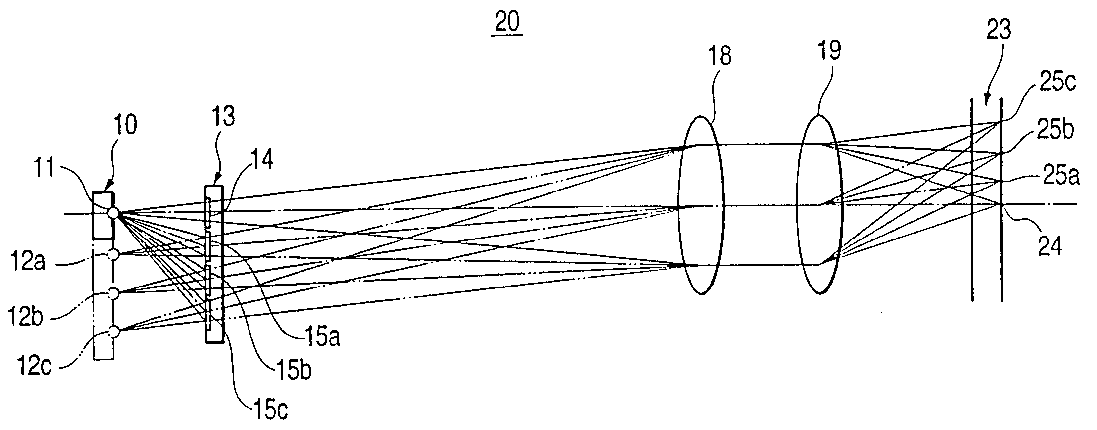
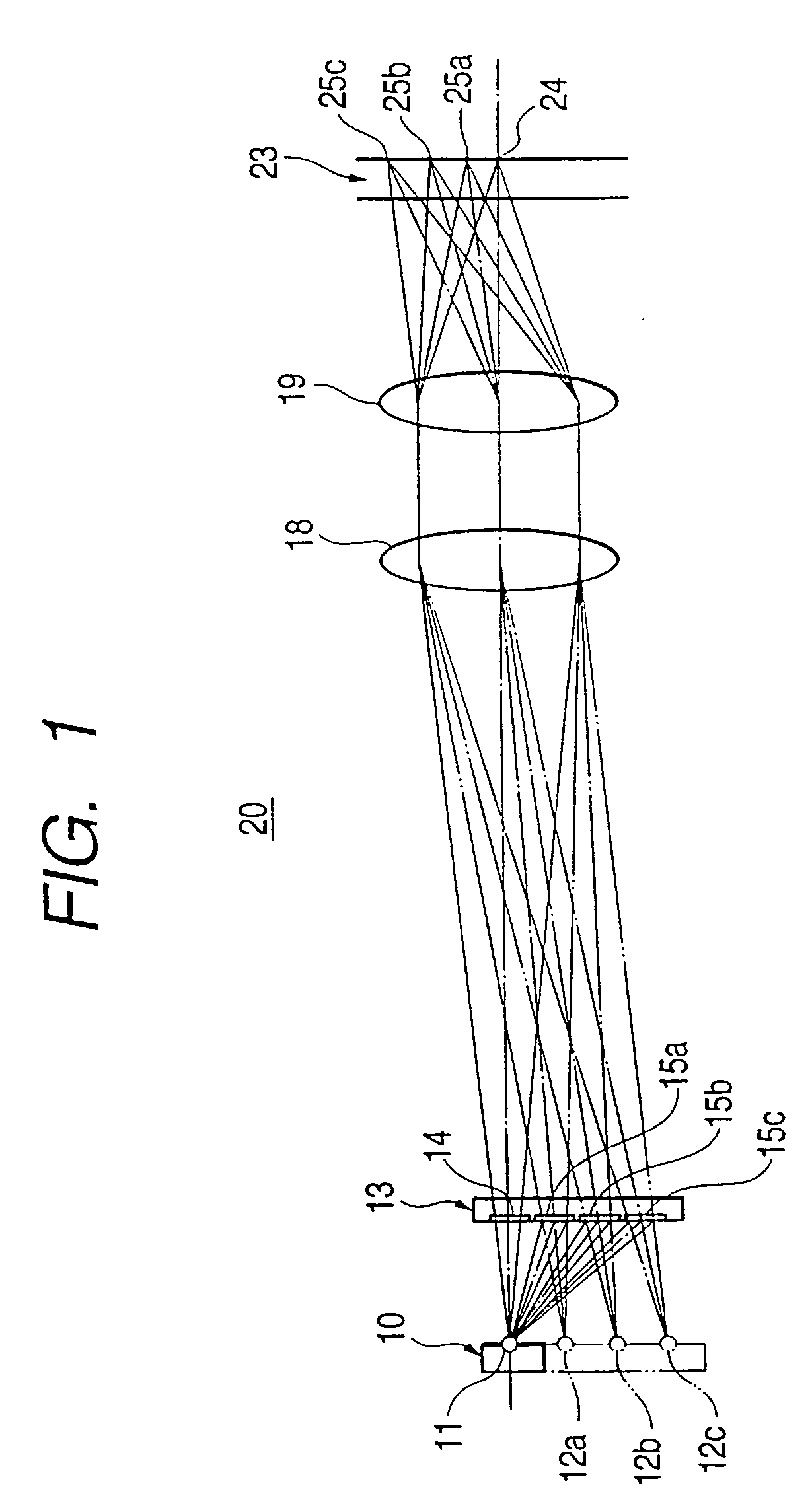
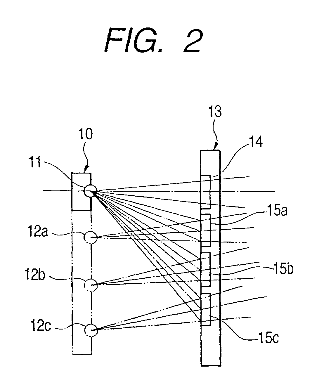
[0031]FIG. 1 is a diagram showing the configuration of an optical pickup device 20, and FIG. 2 is an enlarged view of a portion of the optical pickup device 20 shown in FIG. 1 from a semiconductor laser 10 to a hologram module 13. The optical pickup device 20 has an optical path in a range from the semiconductor laser 10 to an objective lens 19. The semiconductor laser 10 has a single laser chip. Light from a single real laser light source 11 (“real” is used to distinguish from “imaginary” laser light sources 12a, 12b, and 12c) of the semiconductor laser 10 is radiated toward a hologram module 13. The hologram module 13 has one non-diffraction hologram pattern 14 and three diffraction hologram patterns 15a, 15b, and 15c. Light from the real laser light source 11 transmits through the non-diffraction hologram pattern 14 without diffraction, and light from the real laser light source 11 is...


PUM


Abstract

Astigmatism and coma are suppressed in an optical pickup device such that light from a single real laser light source is diffracted and divided by a hologram module into a plurality of light spots which are focused upon a plurality of tracks of an optical disk to read data on the tracks at the same time. A non-diffraction end of fraction hologram patterns of the hologram module are determined so that light diffracted by the hologram module is given inverse aberration of that to be caused by optical elements in optical path from the real laser light source to the optical disk. Another hologram pattern provides a uniform intensity of a light spot formed of a laser light by an optical element.

Description

BACKGROUND OF THE INVENTION[0001]1. Field of the Invention[0002]The present invention relates to an optical pickup device for reading data from, and writing data into, a recording medium such as an optical disk and a card, and more particularly to a multi-beam optical pickup device capable of forming light spots on a plurality of tracks of a recording medium at the same time.[0003]2. Description of the Related Art[0004]In one of the methods of reading at the same time data recorded on a plurality of tracks of a recording medium such as an optical disk, light is emitted from an optical pickup device and focussed upon respective tracks of the recording medium, and light reflected from the tracks is detected with respective photodetectors. Methods of forming a plurality of light spots as illustrated in FIGS. 7 and 8 are known. Basics of these methods will be described with reference to FIGS. 7 and 8 in which elements similar to those of the embodiments to be described later are represe...

Claims


Application Information

Patent Timeline
IPC IPC(8): G02B5/32G11B7/00G11B7/09G11B7/1353G11B7/14
CPCG02B5/32G11B7/14G11B7/1353G11B7/0903
Inventor HIRAGA, TAKAYOSHIMIYAZAWA, HIROSHISINZOU, TOHRU
Owner RAKUTEN INC
Learn More